With the development of China's economy, the number of intelligent buildings in the city has increased. Most of these buildings use central air-conditioning to provide a comfortable office or living environment. However, the problem of high energy consumption in central air conditioning is also restricting the development of central air conditioning. Therefore, energy saving and high efficiency are important issues in central air conditioning systems. The design of the central air-conditioning system of an office building is introduced below to introduce the design of the system in energy-saving and efficient applications.
1 system composition
1.1 The composition of the central air conditioning system
The central air conditioning system is mainly composed of a cold heat source, a chilled water system, a cooling water system, a cooling tower, and an air conditioner end. Different from the general central air conditioning system, the cold source of the system is provided by the water cooling unit. The heat source is realized by using the municipal steam to exchange heat through the hot plate to increase the circulating water temperature. Two 130KW compression chillers are used to provide a cold source for cooling; two sets of hot plates are used for heat exchange to increase the circulating water temperature for heating. The arrangement of the cold and heat source achieves a better energy saving effect. At the end of the air conditioner, there are two types of fresh air conditioning unit and fan coil. The new fan unit is mainly used to ensure the quality of indoor fresh air and control the temperature and humidity of the supply air. The fan coil provides cooling capacity and heat to the room through heat exchange.
1.2 The composition of the control system
At present, the central air conditioning control methods are: relay control, programmable logic control (PLC control), direct digital controller (DDC control), and more advanced is the use of construction equipment automation system (BAS) for central air conditioning and other construction equipment Monitor and system integration. The relay control system has been gradually eliminated due to its high failure rate, complex system and high power consumption. The traditional central air conditioning control method uses DDC control mode to connect various temperature and humidity detection points and control points to multiple DDCs for multi-point monitoring. However, due to the large number of modern intelligent building floors, multiple sets of central air-conditioning equipment are located on different floors, and the temperature and humidity detection points are distributed in each room. The DDC method is used for control, such as complicated lines, inconvenient construction, waste of resources, real-time and reliability of the system. High disadvantages. PLC control integration is lower than DDC, can be freely written, low price, reliable operation, strong anti-interference ability, easy to use and maintain, these advantages make it widely used.
The field equipment of the central air-conditioning system has a Siemens S7-200CPU226PLC as the main controller; two EM223 digital input and output modules, respectively 32DI/32DO and 8DI/8DO; one EM2318AI analog input module; one EM2324AQ analog output module An EM321RTD RTD input module provides two analog inputs; one MP277 touch screen is the most advanced. The host computer is responsible for monitoring and controlling the operation of the entire system, real-time recording of each parameter, and saving it into the real-time database. The structure of the system is shown in Figure 1:
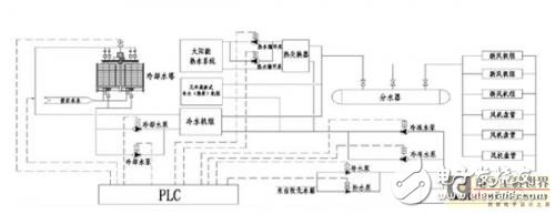
Figure 1 Central air conditioning system structure
2 system applications and functions
2.1 Application and function of chiller
The chiller provides a cooling source for the entire system. After the chilled water circulation system passes through the chiller, the circulating water temperature is lowered. Then, the end of the air conditioner is supplied through a chilled water pump and a water collector. As the development of chillers has matured, this article does not describe its internal workings. In order to meet the demand of different cooling capacity, on the basis of the maturity of the chiller, precise group control of the input quantity and cooling capacity of the chiller is carried out to achieve constant temperature control and balance of power consumption. Compared with the central air conditioning system of a single chiller, group control has more cooling redundancy and more energy-saving operation strategies, which can meet the different requirements of the building group for different periods of cooling capacity.
2.2 Control system selection features and functions
The control system consists of S7-200 series PLC and HMI equipment. In terms of selection, due to the strong stability of Siemens PLC, for central air conditioning group control, there is no need for a lot of redundancy. So you can choose Siemens S7-200 series PLC to take the control part. The on-site temperature and flow are collected by the Siemens EM231 module to calculate the current system cooling capacity. The conveying capacity of the cooling capacity is adjusted by adjusting the rotational speed of the chilled water pump. Because the central air-conditioning chiller can automatically adjust its working load through the effluent water temperature and the return water temperature. Therefore, such control is handled by the chiller itself and does not interfere with the group control PLC.
When the cooling demand of the building group is large, the group control PLC calculates the current required cooling capacity through the differential pressure signal and the flow rate, which is greater than 80% of the rated cooling capacity of the current chiller. If it is greater than, the chilled water effluent temperature and back Whether the water temperature comparison is greater than the allowable set value (such as whether the chilled water outlet temperature is greater than 7 ° C, whether the return water temperature is greater than 12 ° C), if greater than this value, and the current first group of chillers have been operating at 80% of the rated state , the machine operation is carried out to put another chiller into operation. During the operation of the system, if the calculated cooling capacity of the system is less than 80% of the rated cooling capacity of the chiller minus 1, the effluent water temperature and the return water temperature are below the set value. Then you can perform the down operation. Stop a chiller in the system.
In summary, the main function of the S7-200PLC of the control system is to calculate the cooling capacity of the system to achieve the purpose of adding operation and reducing operation. Using such a control system, combined with multiple small power chillers, a group control system. It makes the cooling capacity of the building group easier to meet the requirements, and can always keep running in the same way that the required cooling capacity is equal to the consumption cooling capacity. Improve the comfort of central air conditioning and prevent energy waste.
Since the system control sections described herein are placed on the bottom of the building (-1st floor). Therefore, when selecting a monitoring and control mechanism, choose to use a touch screen (MP277-10 inch) that is more suitable for the current environment as the main equipment. In addition to basic control and monitoring functions, this touch screen meets system reporting and data statistics and meets industry standards.
2.3 chilled water circulation system
The chilled water circulation system functions to transfer cold or heat throughout the system. Three 37KW variable frequency speed control motors are used as the power source. During the refrigeration process, the chilled water pump delivers the chilled water from the chiller to the end of the building for heat exchange. The same is true in the heating process.
The difference is that the three chilled water pumps in this system are driven by a MM440 inverter. A method of driving multiple motors by a variable frequency water supply in a constant pressure water supply. Only one pump is always in the variable frequency speed regulation state, which can effectively reduce the hardware cost. For the power frequency and frequency conversion of the pump, it is also done by the group control PLC.
2.4 cooling water circulation system
During the operation of the chiller, the chilled water return water temperature has been involved in heat exchange at the end of the air conditioner. During the heat exchange process, the water temperature rises. The chiller cools the chilled water temperature by heat exchange. The heat generated during the cooling process is released by the cooling water circulation system. The cooling water circulation system brings the heat generated in the heat exchange of the chiller into the cooling tower. Released by a cooling tower. In this example, the cooling water circulation system consists of two cooling water circulation pumps and two cooling towers. All motors are individually controlled by the chiller internal program and do not interfere with the group control system.
2.5 hot plate replacement part
The system uses a hot plate to exchange internal steam to heat the water temperature to achieve heating. The chilled water circulation system conducts heat to the end of the building. Due to the continuous implementation of the measurement of heating steam in the later countries. Therefore, the municipal steam heating end is controlled by a flow meter and an adjustable proportional valve. Statistics on traffic and the amount of traffic can be adjusted. The regulation of municipal steam and the frequency regulation of the chilled water pump in the heating cycle system achieve the purpose of preventing energy waste. The above control part is also completed by the group control PLC.
During the heating process, the group control PLC determines the amount of pump input and the degree of opening of the proportional valve at the municipal end by the difference between the return water temperature and the outlet water temperature. The above control is implemented by PID.
3 system function necessity summary
In the implementation process of this system, based on the current technology of the chiller in the central air-conditioning industry, the technology of the chiller has become more mature, and the distribution and energy management optimization of the cooling and heating of the building group is aimed at using multiple low-power (relative to the total Refrigeration power) The chiller is a system-distributed cold source, and then group control is used to achieve a wide range of adjustable cooling capacity and improved energy utilization efficiency.