In this paper, a tilt angle measuring device based on digital MEMS (Micro Electro Mechanical System) accelerometer ADXL213 is proposed. The device uses a duty cycle modulation circuit to obtain the corresponding digital signal. According to the analysis of the actual motion model, the corresponding mathematical model is established. Utilize the characteristics of the entire system hardware to achieve good actual measurement results.
The inclination of an object in motion is an important parameter describing the motion state and characteristics of an object. It has important significance in the fields of transportation, aerospace and military, and plays a very important role in the positioning and tracking of the target. Therefore, the angle measurement module with moderate development price, high precision and large measuring range has strong practical value.
Based on the analysis of actual motion, this paper establishes the corresponding mathematical model, and uses digital MEMS accelerometer and appropriate hardware circuit and software algorithm to realize an angle measurement module with high cost performance, high precision and large measuring range. Actual operation, and achieved good results.
1. Object research and modelingThe object of this paper is the tilt angle of the whole platform when the object is moving, such as ordinary vehicle locomotives, military vehicle locomotives and marine equipment. During the movement, the entire platform frame will have a certain inclination due to the influence of road surface and slope. These parameters are of great significance for systems such as precise navigation and train travel control.
According to classical mechanics, when the object has an angle with the reference plane, the ratio of the acceleration of the moving direction to the gravitational acceleration and the angle α of the acceleration and the gravitational acceleration when there is no angle are different. According to the decomposition of the force, the gravity acceleration has a component acting in the Ax direction, and Ax = gsinα, so that the inclination angle α = sin-1 (Ax / g). See Figure 1-(a). However, when the object is moving in the direction of the reference plane, its Ax is also a change value, which will make a correct judgment because it cannot distinguish the static acceleration and dynamic acceleration of the object. It is also conceivable to measure by the method shown in Fig. 1-(b), and set Ax to a direction always perpendicular to the moving surface, so that Ax = gcosα, the inclination angle α = cos-1 (Ax / g). This method can only produce a small acceleration change in the Ax direction on a normal road gradient, which is difficult to achieve for the accuracy of the sensor.
Therefore, considering the measurement as shown in Figure 1-(c), using a two-axis acceleration sensor, the two angles are 90° apart, and the two angles are 45° and 135° respectively, when the vehicle is stationary. In the plane, the two axially measured accelerations of the acceleration sensor: Ax = Ay = 0.707 g.

Figure 1 measurement mechanics schematic
When the vehicle accelerates on a plane, the two axes of the acceleration sensor measure two equal-sized, opposite-polarity acceleration changes, while (Ax+Ay) remains unchanged, for example, when the vehicle accelerates forward, Ax Increase and Ay decreases.
When the vehicle is tilted, the tilt angle α = cos - 1 [0.707 (Ax + Ay) / g]. However, in actual situations, it is almost impossible to make the acceleration sensor and the radial direction of the vehicle exactly 45° due to measurement, installation, etc., so it is necessary to first measure the angle between the acceleration sensor and the radial direction of the vehicle during system initialization. β, according to the formula β=arctan(Ay/
Ax) Calculated.
The final tilt angle thus obtained is: α = cos-1 [(Axsinβ + Aycosβ) / g]. According to this mathematical model, the change in angle can be measured very well. Therefore, in actual use, software and hardware are used to design according to the model to achieve a small angle measurement.
2, system designAccording to the above object research and modeling analysis, and start the system design based on actual needs. In the design process, the corresponding hardware is selected according to the algorithm design, and the hardware is selected for analysis, and finally the required hardware circuit is determined, and then the corresponding software is compiled to complete the whole design.
2.1 Hardware Design
The design uses the ADXL213 chip, which uses advanced MEMS technology to etch a polysilicon surface micromechanical sensor in the same silicon and integrates a sophisticated signal processing circuit. The signal processing circuit converts the analog signal generated by the surface micromechanical sensor into a duty cycle modulated (DCM) digital signal output.
This duty cycle modulated signal can be processed directly using a microcontroller or computer. When data processing is performed by a single chip microcomputer, a counter is used to measure the square wave period T2 and the pulse width T1. Its calculation formula: AX=(T1/T2―ZeroBias)/SensiTIvity; ZeroBias=50%, SensiTIvity=30%/g, T2=Rset/125. The ADXL213 measures static acceleration as well as dynamic acceleration with a maximum measurement bandwidth of 2.5 kHz. The bandwidth (W) is determined by the parameters of the low pass filter. It satisfies the following relationship: W = 1/2πRFCF. Where: RF is the resistance value of the filter, that is, the resistance integrated inside the chip; CF is the capacitance value of the filter. It can be seen that the bandwidth is mainly determined by CF. In the actual design process, according to the vehicle acceleration-time curve, the bandwidth of the selected filter is 1 Hz, which is not only beneficial for filtering high frequency interference, but also for reducing system noise interference. Since the range of T2 in the ADXL213 is 1 to 10 ms. The DCM output square wave frequency should be more than 10 times of the analog bandwidth, and then combined with the single crystal oscillator to determine the T2 period and the set value of Rs. Based on the above research, the hardware circuit of the system is designed. In the system, due to the algorithm relationship discussed above, the system needs to be pre-parked on a horizontal calibration surface to install the system. The system will then work according to the software.
2.2 Software Design
As described in the previous algorithm, in the hardware circuit of the system, due to the measurement method of the selected chip, the two mutually perpendicular sides of the circuit board should be at an angle of 45 degrees with the plane, but it is difficult to guarantee a 45 degree angle, so first The actual angle should be tested and stored in a register. In later applications, the initial data can be used as a benchmark to test to ensure the accuracy of the angle calculation. The initial data calibration is implemented in the design by using the self-recovery button pulse to trigger the interrupt call of the microcontroller. In this design, the measurement of the micro angle of the vehicle during driving and the implementation of other auxiliary functions are realized according to the flow programming as shown in FIG. 2 .
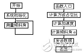
Figure 2 calculation program flow chart
3. Data and conclusionsAfter the above hardware and software design, the entire system function was finally realized, and a series of experiments were carried out. According to the actual situation, in practice, the appropriate filter capacitor is used, the bandwidth is 5 Hz, the noise is about 0.43 mg, and the Rs resistance is set to 1 M. Thus, the square wave period is about 141 Hz. The duty cycle accuracy can reach 0.14%. Through actual measurement, it is found that the output fluctuation is within 1°, that is, less than 17mg. By sampling 20 data, the average calculation finds that the output fluctuation is within 0.5° and less than 8.7mg, so it fully meets the system design requirements and meets the actual needs. Good to achieve the original purpose and requirements of the design. Figure 3 is a test diagram of the actual downhill. The ordinate is the angle and the abscissa is the slope length.
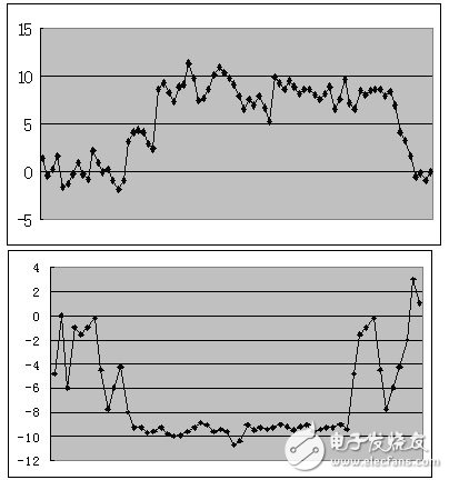
Figure 3 up and down slope angle measured map
1. PC-SVC series Servo motor control Voltage Regulator has the low energy consumption,the over voltage protection,the low voltage protection,the over-current protection,the over-loading protection,the over-temperature protection and so on.It boasts for many kinds of protections,the collection energy conservation and the environmental protection ect.This is a brand-new concept product which possess many new technologies!This series products simultaneously ha applied for many technical monopolies
We already applied many kinds of this products patent, and the technical patent NO: 200720036394.1 and Appearance paten NO: 200730025909.3
2. Use for equipment:
Computer
Test equipment
Light system
Safe alarm system
Ray equipment
Medical equipment
Copy machine
Stereo equipment
Numerical control machine tools
Industrial automation equipment
Color and drying equipment
Test equipment
Hi-Fi equipment
3. PERFORMANCE


Servo Motor Voltage Regulator,Avr Servo Motor Type,Servo Motor Type Avr,Rc Servo Voltage Regulator
zhejiang ttn electric co.,ltd , https://www.ttnpower.com