With the development of the economy and the advancement of science and technology, people have put forward higher requirements for the energy-saving and scientific management convenience of lighting appliances, making the position of lighting control in the field of smart home more and more important. The use of intelligent lighting control systems can better reflect the advantages of energy saving and management, and improve the scientific lighting level of the family. The lighting mode of ordinary households is to turn off the lights during the day and turn on the lights at night. After adopting the intelligent lighting control system, the user can intelligently illuminate according to the number of households in different occasions and different times, and automatically turn on the lighting system and adjust its brightness when needed; The system can also make full use of natural light, while ensuring the necessary lighting, effectively reducing the working time of the lamps, saving unnecessary energy expenditure and prolonging the service life of the lamps.
The intelligent lighting control system can reduce the use time of the lamps and save energy. Extensive economic growth will lead to scarce resources. Therefore, it is imperative to adjust the industrial structure. It is of great significance to promote intelligent lighting systems in the lighting industry. In this paper, the shortcomings of the current method of adjusting the brightness of LED lights based on indoor illumination are added. The human body infrared sensing module and temperature detecting module are added to the lighting system. The temperature detection module can display the indoor temperature in real time, and the human body infrared module can sense whether there is someone in the room. When the infrared sensor module detects that there is no one in the room, the system forcibly disconnects the power supply, which can avoid the energy waste caused by the family owner forgetting to turn off the intelligent lighting system.
1, the overall introduction of the system
The system is mainly composed of APDS-9008 illuminance detection sensor, DS18B20 temperature detection sensor, LCD display, STM32L151, power module and human body infrared.
1.1, MCU introduction
Using ST low-power L series MCU - STM32L151 as the main control chip of this system, its characteristics are as follows:
1) Working conditions:
Operating power range: 1.65 ~ 3.6V or 1.8 ~ 3.6V
Temperature range: -40 to 85 ° C
2) Low power consumption
Sleep mode, low power operation (only 9μA at 32kHz), low power sleep (4.4μA)
Ultra low leakage per I/O: 50nA
Fast wake from stop: 8μs
1.2, APDS-9008 illuminance detection sensor module introduction
The APDS-9008 provides accurate photometric detection under a wide range of ambient light conditions. It has a light sensor with a spectral response close to the CIE standard. Figure 1 is a block diagram of the APDS-9008.
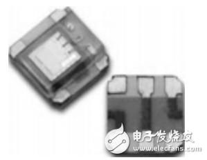
Figure 1 APDS-9008 module diagram
1.3, HC-SR501 human body infrared module
The HC-SR501 is an automatic control module based on infrared technology. It is designed with LHI778 probe, featuring high sensitivity, high reliability and ultra-low voltage operation mode. The technical parameters are as follows:
Operating voltage: DC5 ~ 20V; static power consumption: 65μA; level output: high 3.3V, low 0V; delay time: adjustable (0.3 ~ 18s); blocking time: 0.2s; trigger mode: L Non-repeatable, H repeatable, default value is H; sensing range: less than 120° cone angle, less than 7m; working temperature: -15~+70°C; PCB dimension: 32mm&mes; 24mm, screw hole distance 28mm, screw hole 2mm , Inductive lens size: Diameter: 23mm (default)
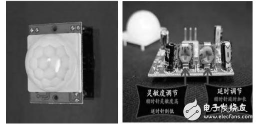
Figure 2 HC-SR501 module diagram
1.4, DS18B20 temperature sensor
Temperature sensing generally uses thermistor as its sensor. The thermistor can measure the temperature range of 40 to 90 °C, but the stability is not high compared with other methods, and the accuracy of general temperature detection is low. For temperature detection signals below 1 °C, the applicability is extremely low, and must be converted into a digital signal by a dedicated ADC to be processed by the MCU.
The DS18B20 digital signal output temperature detection sensor is different from the traditional temperature sensor in that it uses a single bus to communicate with the MCU, which is a direct digital output with fast conversion speed and high scalability. Figure 3 shows the internal structure of the DS18B20 module.
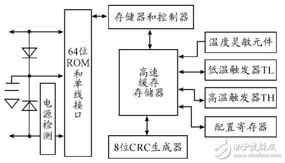
Figure 3 Internal structure of the DS18B20 module
1.5, the overall system architecture
The overall structure of the system includes a HC-SR501 human body infrared module and an APDS illuminance detection module and a DS18B20 temperature sensor. The human body infrared module can detect the number of people in the room. When the indoors are detected, the system starts to work. When the indoors are detected, the system does not work. If the system is working at this time, the system will be forcibly shut down. The APDS illuminance detection module mainly performs intelligent illumination according to the light intensity, and the AO output is output to the STM32L151PC0ADC port for analog-to-digital conversion, and the LED is intelligently controlled after conversion. The temperature sensor will detect the room temperature in real time. The DS18B20 uses the PA1 port for single-bus data transfer, and the temperature results are also printed on the LCD and serial port. The entire system is powered by a polymer lithium battery, as shown in Figure 4.
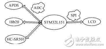
Figure 4 overall system architecture
2, system hardware design
2.1, APDS illuminance sensor hardware design
Figure 5 shows the APDS-9008 illuminance sensor circuit design, in which 1 pin is the power supply (1.6~5V), the system is powered by 5V, and 2 capacitors are added at the same time. 2, 3, 5 feet are NC feet, not connected; 6 feet are analog signal output pins, the output signal is 0~1.9V, and the STM32L151PC0 port is used for analog-to-digital conversion to obtain digital signals, and finally realize intelligent control of LED lights.
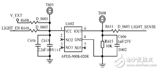
Figure 5 APDS-9008 illuminance sensor circuit
2.2, HC-SR501 hardware design
The HC-SR501 module circuit mainly includes VCC, GND and DO ports. VCC is used for 5V power supply. When it is detected that there is someone in the room, the DO port output is high level, otherwise it outputs low level.
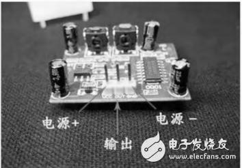
Figure 6 HC-SR501 circuit design
2.3, temperature detection hardware design
The data transmission between the MCU and the temperature sensor mainly relies on the MCU to generate various timing implementations on one bus according to a single bus protocol. Figure 7 shows the specific circuit diagram of the temperature sensor and MCU. VCC is connected to 5V DC, GND is grounded, and OUT is the interface for communication with MUC. A pull-up resistor must be connected to ensure normal communication and idle state. .
2.4, LCD hardware design
The LCD communicates with the MCU using a four-wire SPI protocol. The SPI interface is generally composed of four data lines, including a CS chip select signal line, an SCLK clock signal line, a MISO host input slave output data line, and a MOSI host output slave input data line, and CS is an enable signal. This device is only selected when the enable signal is low. When selected, MOSI and MISO can perform data transmission.
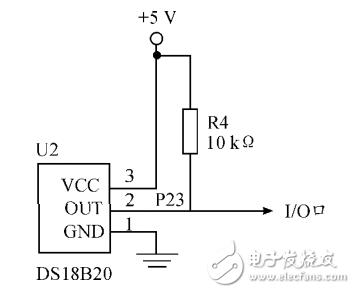
Figure 7 DS18B20 circuit
The read operation is as follows: the first 8 clock masters send the address to the slave, and after the last 8 clock slaves receive the address, the data is returned to the master. When the host sends an address to the slave, it adds 0 to the highest bit of the address to indicate the read. The remaining 7 bits are the internal register address of the slave. After the slave receives the high read flag and the following 7-bit register address. The value of the 8CLK return register will be given to the host to complete a read operation.
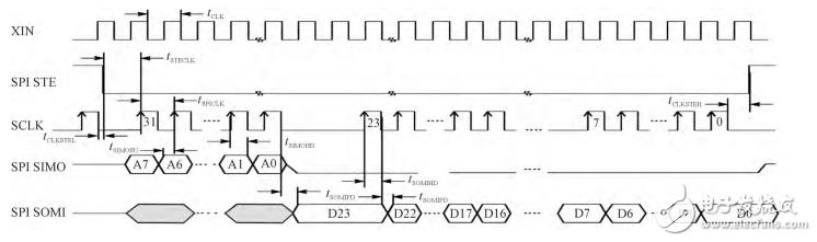
Figure 8 read operation timing
The write operation is also composed of 16 clocks. The first 8 clock masters send 8 bits of the address to be written to the slave, and the last 8 clocks are the 8-bit data sent by the master. When the write operation starts, the same first bit indicates the write flag bit, and the SPI protocol write operation specifies the first bit to be 1. Therefore, at the time of a write operation, 8-bit data is composed of a 1-bit write flag bit and a 7-bit address. When the slave receives the data consisting of the 1-bit write flag and the 7-bit address, it waits for the data sent the second time, and writes the data sent the second time to the address register just to complete a write operation.
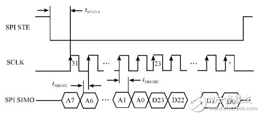
Figure 9 write operation timing
LCD liquid crystal display is mainly used for real-time display of temperature. Figure 10 is a detailed circuit diagram of the LCD.
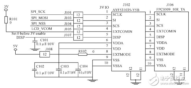
Figure 10 LCD circuit
2.5, power management
The system is powered by a lithium battery. First, the 5V voltage output from the MiniUSB is directly supplied to the lithium battery charge management chip, which is used to charge and manage the lithium battery. The chip is a complete single-cell Li-Ion battery with a constant current/constant voltage linear charger with a charging current of 1A. When the input voltage is stopped, the chip automatically enters a low current state, reducing the battery leakage current to less than 2μA. The lithium battery has a charging voltage of 4.2V and a capacity of 500mAh.
Since the output voltage of the lithium battery will drop during the discharge process and the system operates at 3.3V, a low-dropout regulator is required to ensure the normal operation of the system. The output voltage of the voltage regulator chip is stable at 3.3V, and can output 400mA current. The voltage difference can reach 75mV at the lowest. The peripheral circuit is simple and can meet the requirements. To charge and save data in a timely manner, the system performs battery fuel gauge monitoring.
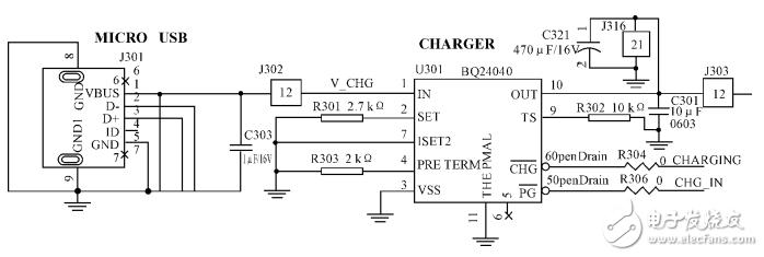
Figure 11 power management circuit
3, system software design
3.1, intelligent lighting software design
Illumination detection is performed using ADC and DMA methods. The ADC can convert analog voltage directly into a digital signal for easy memory storage and transfer. The software design flow is as follows: first initialize the ADC and DMA, let the ADC work in DMA mode; HC-SR501 human body infrared sensor performs indoor environment detection, if there is someone in the room, then data transmission, otherwise it will be detected. When a person is detected in the room, the ADC obtains the voltage value on the bus and then automatically converts it into a 12-bit digital signal to intelligently control the indoor LED light. At this point, the DMA sends the ADC-converted digital signal to the memory. During this period, no CPU intervention is required, which saves CPU resources to obtain temperature. The software flow is shown in Figure 12.
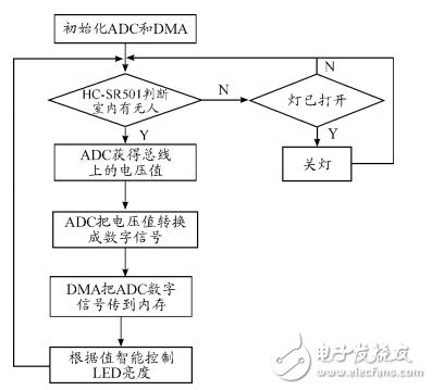
Figure 12 Intelligent lighting software design process
3.2, temperature detection software design
First initialize the DS18B20 to allow the communicating parties to reach a basic communication protocol. Since only one DS18B20 temperature sensor is hung on the bus, the ROM is directly skipped and the temperature conversion command is issued 0x44h. After that, the DS18B20 prepares the temperature data and waits at least 750μs before reading the temperature. After 750μs, re-initialize, read the data already prepared in the memory, and then calculate the temperature, send the temperature data to the serial port and LCD display.
Since the temperature does not change relatively, the timer is used to acquire the temperature. The program is interrupted every 2s, that is, the temperature detection process is performed every 2s. The temperature detection software design flow is shown in Figure 13.
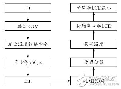
Figure 13 Temperature detection software design flow
4, system implementation
4.1, system meter test software design
In order to test the system, the program designed the system test software. The temperature signal is obtained by the timed interrupt method, which is obtained once every 2s, which can save CPU resources and obtain the latest temperature value in real time. The intelligent illumination is interrupted once for 500ms to obtain the current light intensity information to intelligently control the brightness of the LED light. Finally, the temperature information is sent to the LCD and the serial port for display. The system test flow is shown in Figure 14.
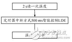
Figure 14 System test process
4.2, system implementation results
The physical map of the system is shown in Figure 15.
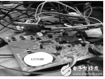
Figure 15 System physical map
As shown in Figure 15, the system consists of a temperature sensor, an LCD panel, a light intensity sensor, a human body infrared sensor, and an LDE lamp.
When the infrared sensor detects someone and the light intensity is low, the LED changes from dark to dark. The serial port data shows the current brightness value. The ADC is 12 bits, so the brightness range is 0 to 4096, and the current brightness is between 70 and 500 cd/m2. The data is correct.
When the infrared sensor detects someone and the light intensity is high, the LED turns from light to dark, the serial port data shows the current brightness, and the value test data is correct.
When the system detects no one, it automatically shuts down the system to avoid forgetting to shut down the system due to human reasons, thus saving energy.
5, the conclusion
The intelligent illumination and temperature detection system designed in this paper, from the perspectives of measurement accuracy, power consumption, and family usability, the selected chips and modules are in line with the principle of low power consumption, with small size, high reliability, high cost performance, and structure. Simple and other features, can be used in smart home systems, with high practical value.
WiFi Camera Module is your popular hidden camera that can be used anywhere to help you. This hidden camera can be used not only at home, but also at work or elsewhere.
WiFi camera is the product of modern high-tech, also known as micro monitor, which has the characteristics of small size, powerful function and good concealment.
WiFi cameras are widely used, suitable for aviation, commerce, media, enterprises and institutions, families and other industries. The emergence of miniature cameras brings convenience to people's lives, and at the same time, some phenomena related to corporate secrets and personal privacy also arise.
WiFi Camera Module,hidden camera for house,hidden camera house,hidden camera with audio,hidden camera in house
Jingjiang Gisen Technology Co.,Ltd , https://www.gisengroup.com