The control signal enters the signal modulation chip from the receiver's channel to obtain the DC bias voltage. It has a reference circuit internally, generates a reference signal with a period of 20ms and a width of 1.5ms, and compares the obtained DC bias voltage with the voltage of the potentiometer to obtain a voltage difference output. Finally, the positive and negative voltage difference is output to the motor driver chip to determine the positive and negative motor rotation. When the motor rotates at a certain speed, the potentiometer is rotated through the cascade reduction gear so that the voltage difference is 0 and the motor stops rotating.
The servo control generally needs a time base pulse of about 20ms. The high level part of the pulse is generally an angle control pulse part within the range of 0.5ms-2.5ms, and the total interval is 2ms. Take 180 degree angle servo as an example, then the corresponding control relationship is this:
0.5ms--------------0 degrees;
1.0ms------------45 degrees;
1.5ms------------90 degrees;
2.0ms-----------135 degrees;
2.5ms-----------180 degrees;
Follower characteristics:
Assume now that the servo is stable at point A. At this time, the CPU sends out a PWM signal and the servo rotates from point A to point B at full speed. In this process, it takes a while for the servo to move to point B.
Hold time Tw
When Tw ≥ △T, the servo can reach the target and there is time remaining;
When Tw ≤ △T, the servo cannot reach the target;
Theoretically: When Tw = â–³T, the system is the most consistent, and the servo moves fastest.
In the actual process, w is not the same, and the limit ΔT during continuous motion is difficult to calculate.
If our servo 1DIV = 8us, when the PWM signal changes in order of minimum change (1DIV = 8us), the servo has the highest resolution, but the speed will slow down.
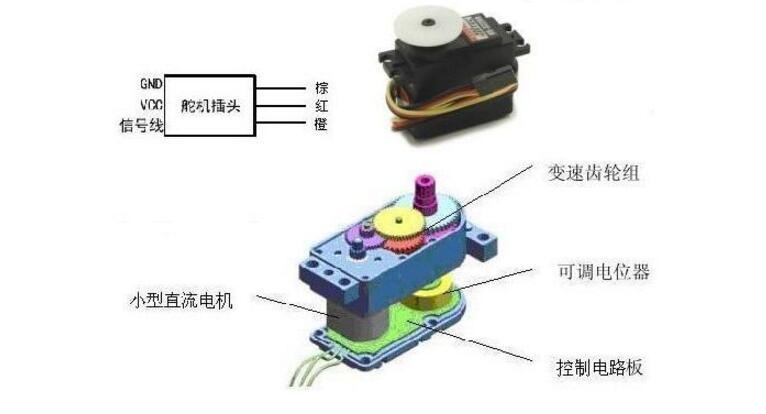
Steering gear: The steering mechanism of the car. That is, control the car's steering. Its characteristics are compact structure, easy installation and debugging, simple control, high torque, low cost and so on. The main performance of the servo depends on the maximum torque and working speed (usually in seconds/60°). It is a position servo driver for control systems that require constant changes in angle and can be maintained. In the robot's control system, the servo control effect is an important factor in the performance. The servo can be used as a basic output actuator in MEMS and aeromodelling, and its simple control and output are easily interfaced with the microcontroller system.
Composition: rudder disk, reduction gear set, position feedback potentiometer, DC motor, control circuit, etc.
Working principle: control signal → control circuit board → motor rotation → gear set deceleration → rudder plate rotation → position feedback potentiometer → control circuit board feedback.
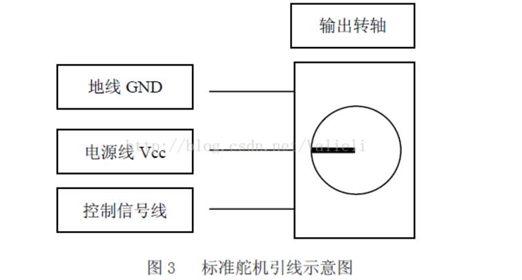
Input line: middle red - power line Vcc; black - ground GND; white / orange - control signal line
Signal: pwm signal, in which the pulse width is from 0.5-2.5ms (period is 20ms), and the corresponding rudder disk position is 0-180 degrees, which shows a linear change.
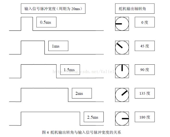
That is, pwm waves with different pulse widths, the servo will output different shaft rotation angles. Therefore, to control the corner of the car, we must control the pwm waves that output different pulse widths.
PWM: Pulse Width ModulationPrinciple: control the on-off of circuit components, so that the output will get a series of pulses with equal amplitude. The pig's pigtails can look like pwm waveforms with equal pulse widths. That is not equal, you can see a row of people with equal height but different weights and leans as pwm waveforms with unequal pulse widths. For example, here is a simple circuit:
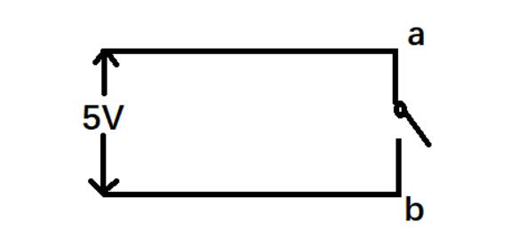
We use 5s as a cycle. In each 5s, the first 3s switch is turned on, and the second 2s switch is closed. The ab terminal voltage will change as follows:
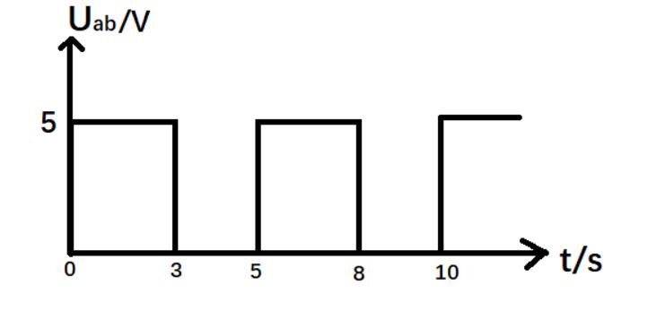
The on-off of the circuit element is controlled so that the output receives a series of pulses of equal amplitude.
In this example, the input signal has a pulse width of 3s and a period of 5s.
Repeat: So to control the corner of the car, we must control the pwm waves that output different pulse widths.
PID control: A regulator control law is proportional, integral, differential control. Among them: P: Proportion, I: Integral, D: Derivative
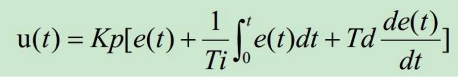
In the formula, Kp is the proportional coefficient, Ti is the integral time parameter, and Td is the differential time constant.
The significance of each parameter:Kp: Proportional coefficient. Increasing the scale factor generally will speed up the system's response.
Ti: Integral time constant. In general, integral control is usually used in conjunction with proportional control or proportional derivative control to form PI or PID control. Increasing the integral time constant (integral weakening) is beneficial to small overshoot, reducing oscillation, making the system more stable, but at the same time prolonging the time for the system to eliminate static errors. Too small integration time constant will reduce the stability of the system and increase the number of oscillations of the system.
Td: derivative time constant. General differential control and proportional control and proportional integral control are used in combination to form PD or PID control. Differential control can improve the dynamic characteristics of the system.
The PID control method is commonly used in two ways:1. Incremental PID
The so-called increment is the difference between the current control volume and the last control volume. Incremental PID is a control algorithm that performs PID control of incremental control variables.

(Note: Kp-"P,Ki-"I,Kd-"D,e array-"error array,
e[n]-"this difference, e[n-1]-"the last difference, e[n-2]-"the last difference)
For example, an incremental PID can be applied to a motor.
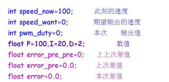
Assume that the pwm value of the current motor PID is 5000 (the accuracy is 10000, that is, the duty ratio at this time is 50%). The corresponding speed is 100r/s.
The program issues a command requesting that pwm output be 0, that is, parking is required. (Maybe someone has questions about why it is not a direct procedure to pwm to 0. This is also a method, but because of inertia, the car will stop after a while.)
At this time, we can use PID control method to achieve.
We define several variables in the program:
According to the formula, we write the program:
Void PID()
{
/*
Incremental PID
P=Kp*(error-error_pre);
D=Kd*(error-2*error_pre+error_pre_pre);
I=Ki*error;
Pwm+=P+I+D;
*/
Error=speed_want-speed_now; //speed_now can be obtained by encoder value etc.
Pwm_duty+=(int)(P*(error-error_pre)+I*error+D*(error-2*error_pre+error_pre_pre));
// Note the plus sign above and the plus sign is the expression of the incremental PID. We perform PID control on the increment (ie, the formula on the right).
Error_pre_pre=error_pre;
Error_pre=error;
}
When the function is run for the first time, the output pwm is:
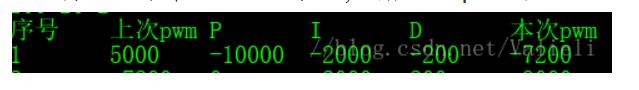
The motor gave a reversed force, and the car moved forward and it stopped quickly.
2. Positional PID
Different from the incremental type, the position type PID does not need to memorize the control quantity, and calculates the expected pwm directly by calculating the deviation value. formula:
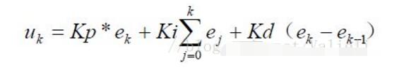
(Note: Kp-"P,Ki-"I,Kd-"D,ek-" This error, ek-1-"error last time)
For example, a positional PID can be applied to a servo. Because the pwm output value of the servo has no relation with the previous pwm output value, the servo needs to quickly turn to an angle.
Assuming that the servo pwm outputs 1000 when the rudder plate shaft is 90°, pwm outputs 0 when the rudder plate shaft is 0°, pwm outputs 2000 when the rudder plate shaft is 180°.
Now that the servo pwm has an output of 1500, we must turn the rudder to the middle.
Here we use PD control, that is, I value is 0 (I value is the integral of the deviation, that is to sum the deviation. We found that the value of I can be omitted when we tested the servo control of the car. PD control is sufficient. Of course, the specific needs Do not need I items to be analyzed and verified in practice).
Code:
Pwm_duty=(int)(P*error+D*(error-error_pre); //The red part indicates that this is a positional PID control
Feedback system:

Uv Vacuum Curing Machine,Uv Protection Screen Protector,Uv Glass Curing Screen Protector,Uv Film Screen Protector Phone
Shenzhen TUOLI Electronic Technology Co., Ltd. , https://www.hydrogelprotector.com