1. Introduction of embedded CPU low power mode
As we all know, low power consumption is already an important indicator to measure an embedded system. As the core of the embedded system, the power consumption of the embedded CPU plays an important role in the whole system. The current popular embedded system CPUs basically provide low power consumption. In general, when the embedded CPU has a working mode and a low power mode, the low power mode can be further divided into an idle mode, a sleep mode, a sleep mode, and the like. After entering the low power mode, the power consumption of the CPU will be much lower. When an external interrupt occurs, the CPU can be woken up. After an embedded system is running, when the system enters the idle state, the CPU can enter the low-power mode, and when an external interrupt occurs, the CPU wakes up and returns to the working mode. Allowing the CPU to be in as low a power mode as possible can greatly reduce the power consumption of the system. However, even if the system is in idle and there is no other work to be done, the system real-time clock interrupt will continue to wake up the CPU, thereby increasing system power consumption. Therefore, you can consider modifying the system real-time clock interrupts to reduce the impact on system power consumption.
2. Analysis of the relationship between system real-time clock and power consumption
In current embedded systems, the system real-time clock is typically a hardware loop counter. An interrupt is issued to the CPU when the hardware counter counts a certain value. The system real-time clock is an important part of the modern multi-tasking embedded operating system, so we need to discuss the relationship between the embedded operating system and the system real-time clock. Today's embedded operating systems generally support multitasking, priority and time slice scheduling. When the embedded OS is up and running, there is usually an IDLE task with the lowest priority, while other tasks should have a higher priority. In the priority scheduling mechanism, it has a chance to run only when other high-priority tasks in the system are blocked. The time slice scheduling mechanism is only valid for tasks of the same priority. That is to say, tasks of different priorities are not scheduled to rotate on a time slice basis, but are scheduled according to priority. Therefore, when the system enters the IDLE task, it can be considered that there is no work in the system to do the CPU, and the system is in the idle state. When the time slice scheduling mechanism is turned on, the embedded OS schedules tasks based on time slices. That is, when a time slice is used up, the scheduler is run to determine the ownership of the next time slice. The basic unit of the time slice is the system TIck, and the system TIck is based on the system real time clock. When the system real-time clock interrupt is generated, the CPU increments the system TIck by one. Whenever the system TIck increases by n (a time slice), the embedded OS will enable the scheduler for time slice scheduling. Therefore, when the time slice scheduling mechanism is turned on, the real-time update of the system tick and the timing operation of the scheduler are required, and the real-time clock interrupt is required to be generated at a high frequency timing. If the time slice scheduling mechanism is turned off, the tasks need only be scheduled according to the priority, so that there is no need to calculate the time slice, that is, the system tick does not need to be updated in real time, and the real-time clock interruption does not have to be generated at a high frequency, and the scheduler also Do not run at regular intervals. This makes it possible to consider extending the interrupt interval of the real-time clock. At the same time, the scheduler does not need to schedule time slices, which can save system overhead. However, after the time slice scheduling is turned off, the system only has priority scheduling. This requires all tasks of the system to be actively blocked, rather than expecting the scheduler to dispatch other tasks of the same priority out of the CPU and let them run. In the current popular embedded operating system, a lot of active blocking mechanisms are generally provided, so it is not difficult to do this. Extending the interrupt interval of the real-time clock allows the CPU to be in a low-power state for a long time until a device interrupt wakes up the CPU. This will greatly reduce the power consumption of the system when it is idle. After extending the real-time clock interrupt interval, there are two issues to consider: one is the system tick and the other is the system delay. The system tick is the interface between the real-time clock and the operating system. The operating system time-related modules and APIs are basically based on tick. In a typical system, the interrupt of the real-time clock is once for each tick. Therefore tick is the smallest timing unit of the operating system. After extending the real-time clock interrupt interval, the system tick will not increase for a long time, so how to ensure the accuracy of the system tick is the most basic problem. By solving the accuracy of the tick, you can isolate the impact of the real-time clock on the operating system. System delay is an important blocking mechanism of the operating system. It is mainly used to let a task actively give up the CPU for a while. The general system delay is based on the system real-time clock. The basic unit of the system delay is tick. When calling delay, the API function will first get the current system tick, then add the time required for delay, form a future delay time point, and then hang the task on the system's delay queue. Therefore, all tasks on the delay queue correspond to their own delay time points. When the system tick exceeds the delay time of a task, the task should wake up. This requires a real-time clock interrupt to wake up the CPU and run the scheduler to re-enter the delay's task into the ready queue. If the real-time clock interrupt interval is extended, the system tick will not increase for a long time, and it is difficult to ensure the accuracy of the delay. At the same time, after the delay time arrives, the task cannot be woken up. To ensure the accuracy of the system tick, it is required to calculate the current system tick by the value of the real-time clock hardware counter each time the system tick is actively obtained. At the same time, synchronization between active acquisition and real-time clock interrupts needs to be guaranteed. For the system delay, the count value of the hardware counter needs to be modified to be the delay time of the minimum delay time point on the system delay queue. This allows hardware counters to be used to accurately control the accuracy of the delay and to use interrupts to schedule tasks in a timely manner.
3. The solution on the I.MX51:
ECOS is an excellent lightweight embedded operating system with a small, compact kernel that supports multitasking, priority and time slice scheduling. Freescale's multimedia chip i.mx51 is based on the ARM Cortex-A8 core and features high performance while supporting the low power capabilities offered by ARM. ARM provides a low power mode, sleep mode. After the ARM executes the instruction WFI, it will go to sleep. In sleep mode, the ARM clock is turned off, and ARM only consumes very low power to maintain its state, which is to enable SRPG (State retaining power gate). When an interrupt occurs, ARM will wake up, resume the clock, and resume execution. The MX51 provides multiple hardware counters. This article uses GPT as the real-time clock. GPT is a loop counter. It can set the count value up to 0xffffffff. Each clock count value is decremented by 1. When the count value is reduced to 0, the interrupt is triggered and the clock is 32KHz. The count value of GPT can be read by ARM at any time, and reading does not affect the count. When the IDLE task is running, IDLE executes the WFI instruction, allowing the ARM to enter a low power mode. If a device generates an interrupt, ARM will be woken up, handle the interrupt and the required task scheduling, and the task will run. Based on the previous analysis, this paper modifies the time slice scheduling and real-time clock system of ECOS. For the time slice scheduling mechanism, it is turned off in the ECOS configuration file. For real-time clocks, its interrupt interval is extended. The system tick is updated in two cases. One is when the ECOS API is called to read the system tick, and the other is when the GPT generates an interrupt. When the ECOS is started, the GPT count value is set to the maximum, so that the GPT takes a long time to generate an interrupt. During this time, the system tick will only be updated when the ECOS API actively reads. The update of the system tick is calculated by reading the count value of the hardware counter. Add a variable pre_hardware_count to the real-time clock class of the ECOS system to record the value of the hardware counter that was last read. Whenever the system API reads the tick, the difference between the value of the current hardware counter and the value of the hardware counter at the time of the last read is the number of tick that has passed between reads. When the real-time clock generates an interrupt, that is, the hardware counter counts to 0, this variable is cleared. This way, you can get an accurate system tick value each time you read the system tick. When there is a task to actively delay for a period of time, that is, when the system delay API is called. The ECOS API function calculates the delay time point of the task and then hooks the task into the system delay queue. Then traverse the system delay queue, find the minimum delay time point in the queue, write the delay time corresponding to the delay time point to the GPT, and let the GPT control the delay time. After the delay time expires, GPT will generate an interrupt. ECOS divides the interrupt handler into two parts, ISR and DSR. Set the hardware counter to the maximum value in the ISR. Then add the system tick in the DSR, re-attach the timed task to the ready queue, and find the minimum delay time point on the system delay queue again, and write the hardware counter. If the system delay queue is empty, the hardware counter is not manipulated again, keeping the maximum value written in the ISR. Finally ECOS will run the scheduler, and if the timed task has the highest priority, then it will get running, that is, wake up. This will ensure the accuracy and timeliness of the system delay. The following figure is a flowchart related to the system tick, delay and scheduler after the modified real-time clock.
The following figure is a flowchart related to the system tick, delay and scheduler after the modified real-time clock.
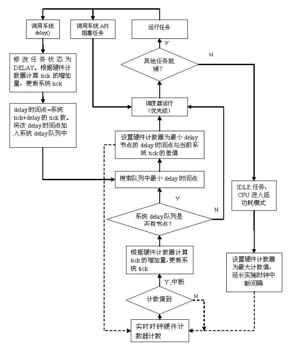
Figure 1. Real-time clock modification flowchart
Below is the experimental data on Freescale's i.mx51.
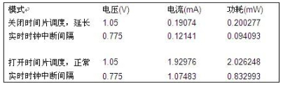
It can be seen that after the time slice scheduling and real-time clock are modified, the power consumption of the system IDLE is reduced by almost 10 times regardless of the voltage point at which the ARM operates. Therefore, extending the real-time clock interrupt interval can greatly reduce system power consumption.
4. Similar method for other systems
The current popular embedded operating systems, Linux and WinCE, are also discussing the modification of the system real-time clock interrupt mode in order to reduce system power consumption. For Linux systems, there is a Less Watts project that implements tickless idle, that is, the ID without tick, which is actually the way to modify the real-time clock. WinCE provides a variable system clock beat Variable Tick Scheduler that changes the system clock beat before entering the idle state, so that the idle state is not woken up by the unnecessary system clock interrupt during the expected time period.
5. in conclusion
It can be seen that by modifying the real-time clock interrupt mode, the CPU can be in the low power mode for a long time in the idle state, which greatly reduces the system power consumption. And the current popular embedded operating systems are actively exploring this approach. I believe this feature will become a must-have feature for embedded operating systems in the future.
Voltage range of the AC power supply is: 100~240V
The wide range makes the charger compatiable with the voltage standard in all countries. With only 15kgs, it is light weight and easy to carry.
Certificate/Conformity to standards:IEC/IECEX/CE/ROSH/IP68/ISO/EX
The combination of layers and modules is convenient and is unnecessary to use a crane for movement."
User safety, electro Enameled covered with paint and electrical protection according to their performance.
Charging Rack,Usb Charging Rack,Phone Charging Rack,Battery Charging Rack
ZHEJIANG HUACAI OPTIC-TECHNOLOGY CO LTD , https://www.win3safety.com