This article refers to the address: http://
1 IntroductionH.264 is based on the coding standards previously developed by organizations such as ITU-T and ISO/IEC. It is the same as most video compression standards in the world today, such as H.264, H.263, MPEG-2. MPEG-4 is a hybrid coding technique that combines block-based discrete cosine transform and quantization. The block-based discrete cosine transform has high compression ratio and low computational complexity. Easy to implement and other advantages. H.264 has the following characteristics: 50% code rate reduction compared to H.263+ and MPEG-4 (SP); strong adaptability to channel delay; improved error recovery capability; complexity gradable design to adapt to different The application of complexity; the introduction of advanced technology, including 4 × 4 integer transform, intra-frame prediction in the air domain, 1/4 pixel precision motion estimation new technology brings higher coding ratio, and greatly improve the complexity of the algorithm. Therefore, H.264 technology has been widely used in codec devices for high definition video.
The entropy decoding, inverse quantization, inverse transform, intra prediction, inter-frame luminance interpolation, inter-frame chroma interpolation and deblocking filtering of the video decoding algorithm are called core modules, reducing the waiting time of these core modules to speed up the work of the decoder. It is of great significance. In this paper, on the DSP-BF533 platform, using the idea of ​​software pipeline, a new optimization design scheme is proposed for the collaborative work between software modules.
2 H.264 decoder principle
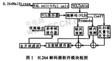
The H.264 encoder structure system consists of the following parts: Network Data Extraction Layer (NAL), VAL Buffer, Entropy Decoding, Anti-Scan Anti-Quantization Inverse Transform, Inter Prediction, Intra Prediction, Image Reference Frame Buffer, Go Block filtering, as shown in Figure 1. First, the NAL unit data is obtained from the code stream, and the sequence parameter set, the image parameter set, and the image data are parsed by the RBSP. The data and parameters are stored in the VCL buffer and then entropy decoded in the video coding layer (VCL Table). The Entropy Decoding Module (VLD) parses all parameters and reference image indexes, etc., and provides various control information and residual data. The inverse-quantization inverse transform first converts the one-dimensional data into a two-dimensional array or matrix, and then maps the transform coefficient quantized value sequence to the corresponding coordinates through the inverse scanning process, mainly including the inverse zig_zag scan and the inverse field scan. Then read the data read and judge, intra prediction and inter prediction, then combine all the anti-quantized data of the prediction and inverse transform, and finally perform block filtering, which can greatly reduce the block effect caused by prediction and quantization, thereby Get better subjective image quality and objective performance. At the same time, the restored image can also be selected as a reference frame for the subsequent processed image.
3 DSP-BF533 decoder design and optimization
3.1 decoder software design block diagram
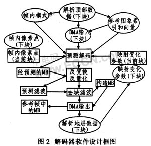
According to the characteristics of DSP-BF533's embedded memory controller (DMA), an integrated DMA decoding process is designed, as shown in Figure 2. Two DMA-related steps are added to the normal decoder, step 1 is to read the data from the off-chip memory; step 2 is to output the processed data to the off-chip memory.
The specific flow can be seen from Figure 2: 1 The top data is segmented for the next macroblock, and the data before the residual data is segmented. At the same time, it provides intra prediction, reference image index and vector for decoding; 2 starts DMA to read the segmented data, which also reads the decoded reference image index and vector; 3 performs intra prediction on the image data; 4 uses bottom segmentation to read Inbound mapping data, inverse transform and inverse quantization; 5 reconstructed image by filtering; 6 output image data to off-chip and on-chip memory by DMA; 7 bottom data segmentation for next macroblock, and then extract mapping data for A macroblock is decoded using mocking.
In order to prevent the DSP core from waiting for the DMA to read the human data, the decoded data is pre-divided from the macroblock into the top data and the bottom data, the top data includes the data before the residual data, and the remaining data is the bottom data. If there is a P frame, the data has been split beforehand, and then the DMA starts. When the DSP core is decoding the current macroblock, the DMA reads in the next macroblock. If the current macroblock reference data needs to be utilized, this data can also be input to the on-chip memory through DMA after decoding. Since the data at the top of the current macroblock has no reference value for filtering the next macroblock, the data at the top of these macroblocks is transferred to the external memory by DMA. The first macroblock of the design does not enter the decoding process, because a series of reference images and parameters are not set in the initial state, so the first macroblock only sets the decoder reference image and parameter row initialization, and is the next macroblock. Decoded for use. The division of the macroblock data and the data reading of the DMA can be performed in parallel in the decoding, that is, the parameters required for the next macroblock can be set and the decoded data can be read when the current macroblock is executed, thereby reducing the waiting time between the modules. ,Improve work efficiency. The above-described processes that can be performed in parallel are represented by elliptical squares in FIG.
3.2 Software Flowing New Algorithm
In many designs, the process of decoding parameter preparation, decoding, and DMA data output are serially executed in sequence. The design is arranged in parallel to perform the three processes in parallel, making full use of the DSP-BF533 instruction parallel execution feature to reduce the software modules. Waiting time between.
Taking the 4×4 macroblock matrix as an example, the coordinates of 4 rows and 4 columns are first marked on the 4×4 matrix, and then the program processing is divided into 5 stages. The states correspond to 1, 2, 4, 8, and 16, respectively, in order for state machine operations, as listed in Table 1. CAVLC is a process of parsing the read data and providing data such as parameters and reference images for subsequent image integration reconstruction. hl_decode is an advanced decoding process, that is, a process of reconstructing images according to prepared conditions. DMA is the transfer process of decoded data. Compare with Table 1 and Table 2: When a new frame of image arrives, the current status label is 1, and only CAVLC is executed. When the coordinate is x=1, y=0, the second state is entered. The status label is 2, CAVLC and hl_decode are executed in parallel; when running to the coordinates x=1, y=1, enter the third state, label is 4, 3 modules are executed in parallel at the same time; when the coordinates y>4, enter the first There are 4 states, the label is 8. Only hl_decode and DMA are executed in parallel. CAVLC has completed preparation for decoding all macroblocks; then judge x>0 and enter the 5th state. The label is 16, and only the DMA module is running at this time.
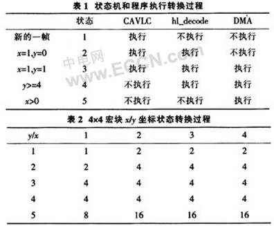
Therefore, the first macroblock is decoded in state 1, after which four consecutive macroblocks are in state 2, and then 11 consecutive macroblocks enter state 3, then one macroblock is in state 4, and the last three macroblocks enter state. 5.
If the execution time A of CAVLC is assumed, the execution time B of hl_decode, the execution time C of DMA, and the total execution time of the common algorithm T=16A+16B+16C; the method time proposed in this paper is T2=A+16B+3C, therefore, obviously Reduced program execution time.
4 test results
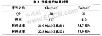
Test Claire.cif and Pairs.cif on the DSP-BF533 test platform. From the results of the test analysis, the optimized results increase the decoding rate and meet the real-time application requirements. The results are listed in Table 3.
5 Conclusion
For mobile video terminal applications, according to the characteristics of DSP, a new software pipeline algorithm is proposed, which makes the module's cooperation more tight, better utilizes the free time of program running, reduces program waiting time and improves decoding rate. Experimental test The program has reached the real-time decoding requirements for CIF images, and further optimized to achieve higher and more reliable decoding efficiency, making DSP-BF533-based design fully scalable from wireless 3G networks, digital TVs, to IP networks. , media storage formats and other different areas.
Correct Electronic Calculator advantage:
14 digits tax calculator,Check Calculator,We use good quality LCD display screen.fonts are clearly visible.Dual power solar power make life recycling.With the first raw material, fine workmanship and repeated testing, ABS is more durable and firm.

Correct Electronic Calculator
Correct Electronic Calculator,Correct Calculator,Correct Scientific Calculator,Check Correct Function Calculator
Dongguan City Leya Electronic Technology Co. Ltd , http://www.dgleya.com