Today's high-speed digital interfaces use data rates that exceed the operating frequencies of many mobile communication devices, such as smartphones and tablets. The interface needs to be carefully designed to manage the local electromagnetic radiation generated by the interface to prevent the interface signal from being interfered by other local RF. This article explores some of the most important techniques for managing high-speed digital interface EMI and shows how they can help solve EMI problems.
Small, low-cost, high-speed serial (HSS) interfaces are especially valuable for mobile devices that must be small, low-power, and lightweight. Electromagnetic interference (EMI) occurs when a mobile device must communicate with a remote network because modern HSS interfaces tend to use data rates that are higher than those used by mobile devices.
In order to achieve successful mobile communications products, all components within these products must perform their own duties and coexist peacefully. This means not only that any undesired RF signal must interfere with any intentionally transmitted RF signal, but also that any intentional RF signal must not interfere with the operation of any other circuit. This is the so-called principle of mutual transparency. The operation of any circuit is transparent - this means that it does not interfere with the operation of any other circuit. It is essential that the specification body must pay special attention to the EMI from the interface to the RF and from the RF to the interface, because no matter how the interface can be “independentâ€, as long as it is susceptible to interference or interference from the transmission, the entire product will not normal work. The MIPI Alliance has developed two specifications that are very focused on mutual transparency.
Electromagnetic science tells us (according to Maxwell's equation) that when an electron moves, it must produce an RF signal. At design time, seven main techniques can be used to manage EMI: isolation, signal amplitude, offset range, data rate, signal equalization, slew rate control, and waveform shaping. These technologies have different functions, and we will discuss them one by one.
isolationPhysical isolation is probably the most obvious technology. For RF signals, if we can "shield" it, it will not interfere with any other signals. Although isolation is never perfect, and at cellular or WLAN frequencies, the actual isolated decibel value is between 20 and 40 dB. Achieving this level of isolation is often essential to address EMI issues. Therefore, it is important to carefully measure the isolation that the IC package and PCB layout can provide.
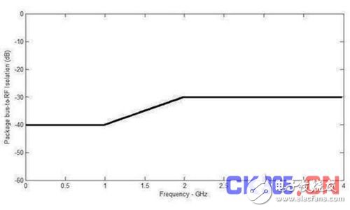
Figure 1: A possible isolation cover for a representative RF package.
Signal amplitudeReducing the amplitude of the interface signal will definitely reduce EMI, but it will not be effective. If the signal amplitude is reduced by half, EMI is only reduced by 6dB. This may be enough to get rid of a close problem, but it also reduces receiver margin and can cause interface errors. Based on this, it is best to use it as a last resort to deal with EMI problems.
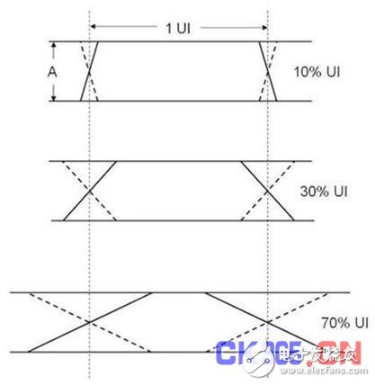
Drift and balanceDrift is the time offset between the two components of the differential signal. Balance is the amplitude match between the two components of the differential signal. These two parameters are basically determined by the interface driver circuit and are best analyzed together. As shown in Figure 2, when the signal is balanced within 10%, the exact value of the signal balance is less important than the EMI effect caused by drift. This means that from the perspective of EMI, when designing the interface driver circuit, the drift is much less than the effort amplitude balance.

Figure 2: Group comparison of signal balance and drift.
The figure shows that managing drift is much more important than getting a very closed signal balance. Even with 2% UI drift, the effect of signal balance error of up to 10% is negligible. Signal balance becomes important only when the drift is 100% (an unlikely situation).
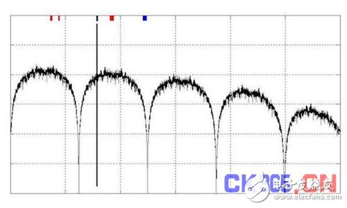
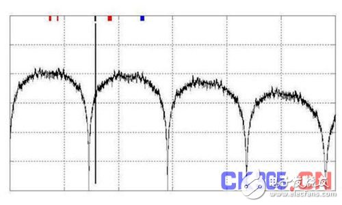
Data transfer rateThe RF spectrum of a digital signal has different characteristics. From an EMI point of view, the most important is the spectral zero value of the data rate and its integer multiple rate. Figure 3 clearly shows these spectral zero values. These zero values ​​exist independently of any signal filtering. It is a viable option to change the data rate instead of moving the spectrum zero to near a radio frequency receiver band to remove EMI into the receiver. This is especially important for GPS receivers that must recognize extremely weak signals sent back by multiple satellites. Figure 3 shows this technique for helping to protect a GPS receiver, with data rates changing from 1.248 Gbps (Figure 3a) to 1.456 Gbps (Figure 3b).
(a)
(b)
Figure 3: Changing the interface data rate moves the spectrum zero value. This is a particularly effective way to reduce EMI in a particular frequency band without any filtering.
Slew rateAll the necessary information carried by the interface is located in the main spectrum. The spectral side lobes carry data waveform transformation information, not the data itself. For EMI generated by the energy of the side lobes (the frequency of these side lobes is higher than the data rate), it can be suppressed by reducing the slew rate of each waveform transformation. This is effective because the total bandwidth of the unexpected RF signal is not controlled by the data rate, but by the fastest transition (edge) of the data waveform.
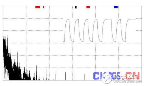
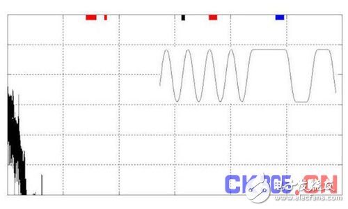
Figure 4a (top) illustrates how this technique does affect the "eye diagram" of the interface signal. Although the width of the fully open eye is narrowed, the separation between the top and bottom of the eye is not affected. This is the price that must be paid for using this filtering technique.
Please note that the slew rate control only reduces the sidelobe amplitude. Any effect on the main lobe is negligible. This has its advantages and disadvantages: the benefit is that this means that slew rate control does not dilute the data content. The downside is that this technique is ineffective only when the interference frequency comes from the main lobe. For this reason, applications such as MI-Link's MIPI Alliance DigRFSM tend to use multiple channels each operating at a lower data rate than a channel operating at a higher data rate.
(a)
(b)
Figure 4: Effect of slew rate control on the higher frequency side lobes of the differential signal: top) definition of the edge transition time of the eye diagram; bottom) the spectrum corresponding to the transformation shown in the a diagram.
Waveform shapingThe direct method of implementing slew rate control is to adjust the current source charge and discharge capacitors. This produces a linear transformation as shown in Figure 3 and Figure 5a below. Other waveform shapes do affect the EMI value, and the results are good or bad. For example, Figure 5b shows the effect of an exponential waveform obtained by simple RC filtering. Here, EMI has actually become more serious. The reason is that at the beginning of any transformation, the exponential waveform forms a sharp corner, even if the end of any transformation is smooth. But at the end of the transformation, the damage has already occurred.
Figure 5c shows that the spectral clamp performance is greatly improved when all sharp corners are removed from the interface waveform. Removing sharp corners is the primary goal of waveform shaping, so it is sometimes referred to as waveform curvature limitation.

(a)
(b)
(c)
Figure 5: Spectral variation of EMI signals with signal transformations of different waveform shapes: a) linear transformation, b) exponential transformation, and c) filtered waveform. The exponential transformation actually has the worst ability to suppress EMI.
Technical combination punchAll EMI management techniques begin with maximizing physical isolation. In addition to isolation, different technologies are used depending on the specific problems encountered by the Interface Standardization Committee. Below are two examples from the published MIPI standard.
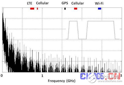
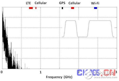
The MIPI Alliance's M-PHY specification is an HSS link that uses low amplitude differential signals. Because data rates are higher than many cellular and other wireless communication frequencies, methods such as data rate selection, slew rate control, and drift boundaries are used in combination to reduce EMI that occurs at the internal (including possible monolithic) RF receiver inputs. Figure 6 is an example of this improvement.
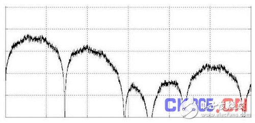
Figure 6: The MIPI Alliance's M-PHY interface combines drift boundary and slew rate control techniques to minimize high frequency EMI. This result is compared to the spectrum in Figure 4b.
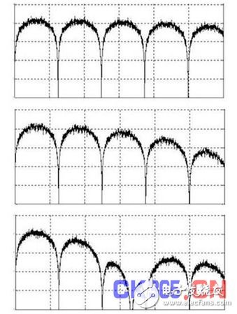
The MIPI Alliance's RF Front End (RFFE) interface has different issues and uses different technologies to manage EMI. RFFE applications require large values ​​of single-ended signals, even when the interface is operating close to sensitive RF inputs. The combination of technologies used here first uses the lowest data transfer rate consistent with the application requirements. We then apply curvature control to the interface waveform to ensure that any EMI is limited to the operating frequency below the local RF. Fig. 7 is an example showing the effect of the action.
(a)
(b)
Figure 7: The MIPI Alliance's RFFE interface combines data rate selection and waveform shaping techniques to control unwanted RF signal bands below the primary wireless communication band: (top) 26MHz data rate has caused most of the signal energy to be at low frequencies, and (Bottom) A small amount of curvature control was implemented at the beginning and end of each conversion, significantly improving EMI suppression performance.
to sum upDesigned EMI management is a key component in achieving transparency between the interface and receiver within a mobile device. The specification committees that define these interfaces, such as the MIPI Alliance, are best placed to control this capability.
Experience gained from the development of M-PHY and RFFE interface specifications that emphasize mutual transparency has shown that some techniques are effective and somewhat less effective in reducing EMI. The most effective technology so far is good physical isolation. The second is to limit the drift allowed by the differential signal and to avoid the use of RC filtering that can cause the exponential interface waveform. For reducing EMI, the use of waveform shaping techniques to reduce sharp corners on the interface waveform is a particularly effective method.
Selecting the data rate is a technique that does not require filtering. Since EMI from digital waveforms have spectral zero values ​​at this data rate and all of their integer multiple rates, it is also very effective to place these zero values ​​near the frequency band of interest. Last but of course not unimportant, is to reduce the amplitude of the interface waveform. This technology has little impact on EMI.
Indoor Line Array,Column Array Speakers,Box Line Array 10 Inch,Mini Line Array
NINGBO LOUD&CLEAR ELECTRONICS CO.,LIMITED , https://www.loudclearaudio.com