Abstract: Based on the discussion of automatic gain control (AGC) circuit, the application of automatic gain control in Konka color TV receiver is introduced. And give detailed solutions and measures for the failure of color TV receivers.
Keywords: color television receiver; automatic gain control (AGC) circuit; fault; overhaul
This article refers to the address: http://
In a color television transmission system, the strength of the received signal may vary greatly due to the influence of different receiving environments or external interference and aging of the device. When the signal is weak, the contrast of the image becomes small, the sharpness is poor, and the synchronization is unstable, and the image cannot be imaged. The stronger signal will cause the post-stage amplifier to enter the saturation region and the cut-off region, causing severe distortion of the signal, and the sync pulse will be cut off, and a good image will not be obtained. This will affect the user's normal viewing of the TV program. Therefore, the design and analysis of the automatic gain control AGC (Automatic GainContr01) circuit for color TV receiver is introduced in detail.
1 Automatic Gain Control (AGC) Circuit Automatic Gain Control (AGC) circuit plays an important role in early discrete and small scale integrated circuits, and in today's very large scale integrated circuits, generally including the following aspects: image amplitude control Circuit; sound amplitude control circuit; chrominance signal control circuit.
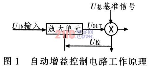
The working principle of the automatic gain control (AGC) circuit is as shown in Fig. 1. Set a reference level (U base). Through the detection circuit, the gain of the amplifying circuit is automatically adjusted according to the actual situation of the signal level, so that the output is stabilized in the reference. At the level, UOUT≈U base.
2 Color TV Receiver Failure Analysis If the color TV receiver control circuit fails or fails, the TV may experience problems such as no image, picture reversal, noise on the picture, small accompanying sound or distortion, no color or light color. Due to the different equipment used by the broadcasting and television transmission systems in various provinces and cities in China, the use of non-standard amplifiers in the transmission process has resulted in different reception effects of TV receivers in different regions: some areas can receive normally, while some areas cannot. Receive, so the AGC circuit design is very important.
2.1 Failure caused by improper design of the amplifier circuit The Konka A series TV with Sanyo CA768lO as the main device has the phenomenon of upper twist and field unsynchronization. After the actual operation check, when using this series of TV sets to receive wireless signals. There is indeed an image twisting and non-synchronization phenomenon, and the oscilloscope is used to observe the video output signal, and the line and field sync signals are all compressed, that is, lower than the standard signal amplitude.
However, when using a Konka A-series TV to watch a standard cable signal, the above failure did not occur. Therefore, it can be concluded that it is caused by a non-standard television signal, and the television signal has seriously deviated from the national standard. Figure 2 is a connection diagram of the external circuit of the Konka A series TV.
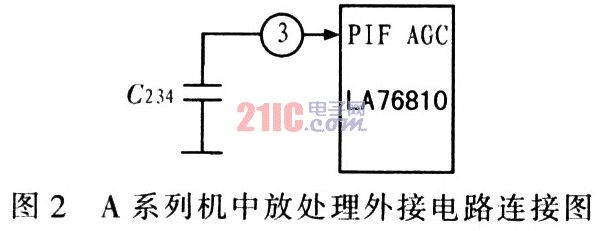
Since the synchronization signal has been compressed, the only way for the non-standard signal is to improve the image IF amplification circuit, that is, by changing the capacity of the AGC filter capacitor to change the control point and the control time of the nucleus circuit, thus separating The TV signal is relatively standard, and the reproduced image can be normal and stable within the controllable range of the TV. Through the test, the C234 was changed from 68 nF to 20 nF, and the fault disappeared. The TV receiving function is normal and the signal reception is stable.
2.2 AGC circuit causes TV white balance debugging crash and data loss Konka's second-generation super TV, which is dominated by ultra-large-scale devices, is manufactured by German Microsystems, model VCT3801, VCT3803. This series of devices combines the CPU and decoder into one, greatly simplifying board layout and facilitating mass production in large scale. However, in actual production, there is a sudden crash when the white balance is automatically debugged, and the color TV that has been debugged has data loss after several times of switching on and off, and the picture is color cast. This has led to a decline in production efficiency, which is only 50% of normal production. Even the barely tuned normal color TV machine has serious quality problems.
1) White balance automatic debugging principle Because the bus technology is used, when the S series TV with the second generation super device is turned on, the CPU will automatically detect the video and R, G, B signals, and make appropriate adjustments to ensure vivid and true colors. . The three signal amplitude data of R, G, and B are stored in a memory, which is determined by the white balance automatic adjustment system before the TV is shipped from the factory. Figure 3 shows the block diagram of the white balance automatic adjustment system.
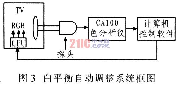
In Figure 3, the CAl00 color analyzer processes the color temperature coordinates of the TV detected by the probe, and obtains the (x, y) value. The (x, y) value is sent to the corresponding control software of the computer, and the value processed by the software is processed. Compared with the reference (x, y) value, a difference value is generated. After the software conversion determines the required R, G, and B amplitudes and sends them to the TV CPU, the CPU immediately adjusts the amplitudes of the video signals R, G, and B, and continuously cycles. Until the (x, y) value detected by the probe is the same as the reference value, the computer stops automatically adjusting and writes the R, G, and B amplitude data at this time into the memory.
2) Analysis of the cause of the S series machine failure After the fault occurs, due to the automatic control of the computer, the cause of the failure may be originally considered to be: the computer host configuration is too low; the color analyzer is faulty; the external interference; the computer and the TV CPU communication have obstacles. However, by the fault detection one by one, the above reasons are basically excluded. Therefore, the SDA machine's mid-stage processing uses TDA4472. By adjusting the RPl20 potentiometer, the device will automatically output the RF-AGC voltage, but the RF-AGC voltage of the TDA4472 output is different due to the inconsistent position of the RPl20 potentiometer. In turn, the amplitude of the video signal is different. Since the amplitudes of the video signals are inconsistent, the CRT brightness of each color television is inconsistent.
In order to speed up the white balance debugging speed when designing the system, the S series TV sets the software learning function. That is, during debugging, the system software automatically extracts the R, G, and B data of the previous TV set, and adjusts it based on this. In this way, due to the inconsistent brightness, the system software has an automatic learning function, which causes the system software to enter a blind spot during debugging, which may exceed the control range of the system software. Once it is exceeded, the whole machine will suddenly crash. Even if the debugging is normal, it is easy to cause the data loss and color cast of the whole machine because it is at the edge of control. To avoid the above phenomenon, the RF signal adjustment is changed to the AV signal adjustment. Avoid the influence of the AGC circuit on the video signal, so the difference between individuals in mass production is not very large, and is within the control range of the CPU.
Through the above adjustments, the fault phenomenon in the white balance adjustment process of the S series machine no longer occurs, which greatly improves the production efficiency and eliminates the quality hazard. Therefore, the role of the AGC circuit should be taken seriously in both the production and the product process.
3 Conclusion This paper introduces the application analysis of AGC circuits in color TV receivers. Carry out detailed analysis of the faults that have occurred, and give corresponding solutions and measures. This greatly improves the production quality and efficiency of color TV sets. Therefore, automatic gain control circuits play an important role in color television production.
Anti-Jamming RC Arc Extinguisher
Anti-Jamming RC Arc Extinguisher
")
Anti-Jamming RC Arc Extinguisher
YANGZHOU POSITIONING TECH CO., LTD. , https://www.yzpst.com