1 Introduction
With the accelerated pace of social life and the gradual aging of the population, cardiovascular disease has become one of the most important diseases threatening human life at the same time. Such diseases often have the characteristics of sudden, transient and dangerous. If they cannot be found in time And treatment will have very serious consequences. The electrocardiogram is a check. The main means and basis for diagnosing and preventing such diseases. For the symptoms of myocardial infarction and arrhythmia, the use of ECG monitors runs through the entire process of treatment and rehabilitation. Due to the traditional ECG-based ECG platform, which is expensive and bulky, it is not easy to move and is mainly concentrated in large hospitals, which brings great inconvenience to doctors and patients. Therefore, in order to reduce cost and volume, this paper designs a new portable multi-bed telemetry ECG monitor based on ARM9 microprocessor. The monitor adopts a 16 / 32-bit high-speed processor S3C2410A chip of ARM920T as the controller core of Samsung company as the system control core. It uses nRF401 wireless transceiver chip to send and receive ECG data. It has low power consumption, small size, High reliability, simple operation and other advantages.
2 System structure
The telemetry ECG monitor can monitor 1 ~ 12 beds at the same time. The block diagram of the system structure is shown in Figure 1. The S3C2410A connected to the PC is used as the central shelter. Its function is to transfer the commands sent by the PC, communicate with the monitoring terminal monitoring each bed, and collect the data collected by each nursing terminal to the central monitoring terminal, and pass it to the PC through the USB port. A portable ECG monitoring terminal monitoring a bed serves as a terminal node. Its function is to collect ECG signals, perform necessary processing on the collected data, and respond when receiving commands from the central monitoring terminal.
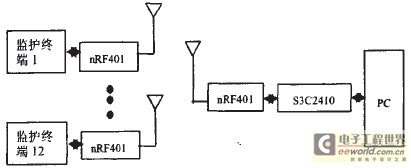
Figure 1 System structure block diagram
3 System hardware design
The system hardware design includes the hardware design of the central monitoring end and the hardware design of each ECG monitoring terminal monitoring a bed. The hardware design of the central monitoring terminal includes the connection between S3C2410A and PC and the connection between nRF401 and S3C2410A. Because the S3C2410A has a USB device controller, it can be connected to a PC via a USB port and get a T of 5V as the voltage. The wireless transceiver chip nRF401 is directly connected to the serial port 1 of S3C2410A. Figure 2 is a block diagram of the hardware circuit of the ECG monitoring terminal monitoring a bed, including the ARM microprocessor S3C2410A, ECG amplification and acquisition circuit, external expanded Nand FLash memory, Power Supply , LCD display, keyboard and nRF401 special line data transmission Modules etc.
3.1 ECG acquisition circuit
The ECG acquisition circuit includes an amplifier, a low-pass filter, and a 50 Hz notch filter. The amplifier of this circuit is composed of a differential amplifier circuit and an amplifier circuit of two stages. The lead system adopts a universal two-electrode method. The right upper chest electrode and the left lower abdominal electrode are ECG sampling electrodes. The right subabdominal electrode is the right leg drive electrode. Since the collected ECG signal is a model-raising signal, a three-amplifier driving amplifier circuit is used as the first-stage amplifier circuit with a gain of about 22, and then the second-stage amplifier circuit has a total gain of approximately 1,000. Because the ECG signal is a low-frequency signal, in order to eliminate high-frequency signals, a low-pass filter with a first-order filter circuit is designed, and the cut-off frequency is 100 Hz. In order to suppress 50Hz power frequency interference, a second-order voltage-controlled voltage source band stop filter, that is, a 50Hz notch filter, is also designed.
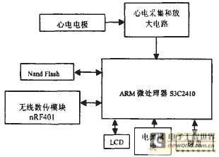
Figure 2 Block diagram of the hardware circuit monitoring a bed
3. 2 ARM microprocessor module
S3C2410A is an embedded CPUS3C2410 based on the ARM920T processor architecture introduced by the two-star company. It provides an 8-channel 10-bit analog-to-digital Converter . The converter converts the analog input signal with a maximum conversion rate of 500ksps to 2.5MHz MD lO bit binary digital coding. According to the AHA standard [3] of the American Heart Association and Nyquist sampling law, when the signal sampling frequency is equal to or twice the highest frequency of the signal, the original signal can be restored from the sampled signal without distortion. The ECG frequency range is 0.05 ~ 100Hz, and the center frequency is about 17Hz, so the sampling frequency is 200Hz, that is, the sampling period is 5ms to meet the requirements. The collected signal is sent to the S3C2410A microprocessor via channel 1. After analysis and processing, the ECG waveform and analysis results are displayed on the LCD screen.
3.3 Wireless transceiver module
The wireless transceiver module uses the monolithic UHF wireless transceiver chip nRF401 developed by Nordic, which works at the end of 433MHzISM (Industrial, scienTIfic and Medical). No license is required for this band. And adopt FSK modulation and demodulation technology, strong anti-interference ability, and use PLL frequency synthesis technology, good frequency stability, data transmission rate up to 20kbDs, transmission distance up to 1000m, fully meet the communication distance requirements of this design. Unlike other RF monolithic chips, nRF401 communicates directly with the MCU through the serial port of the microcontroller, without the need to perform Manchester encoding on the data, which makes nRF401's peripheral components very few, including only a reference crystal and several passive devices, which has a cost Low and good consistency. In this design, nRF401 is directly connected to serial port 1 of S3C2410A.
3.4 Storage, display and keyboard module
In order to realize the large-capacity data storage, the S3C2410A's own Nand Flash controller is used to expand a 16Mx8-bit Nand Flash memory, which can store 12 hours of ECG data. In order to enable users to have an intuitive impression and common sense observation of the collected ECG signals, the LCD controller interface is designed using the S3C2410A's own LCD controller, and a 240x128 LCD display is selected. Used to display the collected ECG signals and some basic parameters. The system has also designed a 4x4 keyboard module, users can switch some basic functions through the keyboard.
4 System software design
The software design of this system is based on the Windows CE operating system. Windows CE is a compressed, highly efficient and scalable operating system designed for various embedded systems and products. It has a multi-linear, multi-tasking, full-priority operating system environment. Because the Window CE operating system itself does not have its own independent development environment, it is necessary to complete the development of the application program on the PC (host machine) to achieve simulation. And cross-compile for ARM embedded devices (target machine) to match the CPU architecture of the target machine, so that the operating system and application software can also run normally on the target machine. Then transplant to each target machine. After the Windows CE operating system is built, it is the implementation of the upper-layer application.
4.1 Program design of central monitoring terminal
Windows CE is a multi-tasking, multi-threaded operating system [6]. The picture shows that the function of the central monitoring terminal is not only a single network communication, but also data analysis and processing, so it does not directly communicate in the main thread. Instead, a separate sub-thread is created in the main thread to wait for the PC's command. After receiving the command, it creates a separate communication sub-thread to communicate with the corresponding terminal node. Wait for the child thread to continue to wait for the PC's command. The communication sub-thread receives the data and performs verification, and transmits it to the PC through the USB port.
Since multiple communication sub-threads may access the shared resource nRF401 at the same time, forming a thread conflict, it is necessary to coordinate the synchronization between various threads. Mutexes (Mutex) is one of the methods provided by the Windows CE operating system to achieve thread synchronization. It is mainly used to coordinate the access of multiple threads to shared resources. The principle is that only threads with mutex objects have access to shared resources. permission. Because there is only one mutex object, it is determined that this shared resource will not be accessed by multiple threads at the same time. First, use the function CreateMutex () provided by the API to create a mutex object, initialized to the FALSE state to identify that the mutex object is not occupied by any thread. The communication sub-thread requests to occupy the mutex object through waitForSingleobiect (). If the mutex object is occupied at this time, the thread needs to wait until the previous thread is released before it can be successfully occupied; if the mutex object is not occupied at this time , You can achieve access to the shared resource nRF401. For example, after the sub-thread responsible for communicating with the monitoring terminal with bed number n obtains the access right to nRF401, the sub-thread will send a 1-byte synchronization signal "n". After the monitoring terminal with bed number n receives the command, "N" is returned as a response. After the communication sub-thread receives the response, after the verification is correct, the two parties start data transmission, and the monitoring terminal transmits the data and its checksum to the central monitoring terminal in the form of a data packet. After the child thread finishes receiving, the communication is ended, and ReleaseMutex () is used to release the ownership of the mutex object, and the access to the shared resource nRF401 is completed, so that other threads can have access to the nRF401. Then verify the received data and make another request to occupy the mutex object. In this way, each communication sub-thread has equal access to nRF401, and the sub-threads are independent of each other, avoiding program deadlock on one connection and improving the overall response speed of the system.
4.2 Program design of monitoring terminal
The program design of each monitoring terminal monitoring a bed also adopts a multi-threaded structure, and performs A / D conversion, necessary processing, storage, display, etc. on the main thread of the ECG signal. Create another sub-thread, set nRF401 as the receiving state, wait for the command from the monitoring center of the receiving center. After receiving the command and verifying the legitimacy, set nRF401 as the sending state and send the response, and read the data from the memory towel and package it. The end verifies the error information, and then resends the data packet.
4.3 Detection of QRS waves
In ECG analysis, parameter measurement and waveform analysis are required to calculate the RR interval and heart rate. First, QRS wave detection is required. In this paper, the four-point average filter method is used to filter the ECG signal first, to filter out the interference caused by power frequency interference, baseline drift, myoelectric noise, and motion artifacts. Its analytical formula is:

It has little effect on the center frequency (17Hz) of the ECG signal, and can suppress high-frequency noise and 50Hz power frequency interference. Then the smoothed first and second order difference values ​​of the filtered ECG signal are used to realize the accurate positioning of the QRS wave in a short time window by using the minimum value of the second order difference value of the ECG signal and the first-order difference zero crossing point . That is, the four-point filtered ECG signal y (n) is first-order and second-order difference, and the location of the minimum value of the second-order difference corresponding to the R wave is found by methods such as refractory period discrimination and amplitude discrimination. Then according to the second-order difference and the time delay relationship between x (n) and y (n), the position of the R wave in the filtered signal and the original ECG signal is obtained. In the first-order differential signal of the ECG signal, the positional relationship between the R wave and the corresponding Q and S waves is: If the R wave is the downward zero-crossing point corresponding to the QRS complex in the first-order differential signal (the value is negative ), Then the Q wave should be the first upward zero crossing (positive value) before the position of the R wave; the S wave should be the first upward zero crossing (positive value) after the position of the R wave. In this way, the position of Q and S in the first-order difference can be detected from the known position of the R wave, and then parameters such as RR interval and heart rate can be obtained according to the time delay relationship. Since the score will increase part of the high-frequency noise, the above calculation is performed after the first-order and second-order differences are processed by smooth movement. The algorithm can suppress the influence of various noises on the ECG signal. After clinical testing, it is under resting and walking conditions. The detection accuracy of the algorithm for dynamic ECG is very high; even in the case of gymnastics and jogging, the accuracy rate is still above 99.8%.
5 Experimental results
Using this monitor, ECG data were collected from 12 volunteers. Experiments show that the monitor can monitor 12 patients at the same time and 1 patient independently, with good real-time performance. The ECG waveform is displayed clearly, and the ECG data is analyzed accurately. When the arrhythmia is abnormal, it will automatically alarm and store and playback it. The wearer can get better monitoring activities within a radius of 100 meters. It is powered by 2 batteries and can continuously monitor for 20 hours.
6 Conclusion
In this paper, a new portable multi-bed wireless telemetry ECG monitor based on ARM9 microprocessor is designed. The monitor has high hardware integration, small size and low power consumption, which is convenient for patients to carry around without affecting the daily activities of patients. So that patients have better monitoring. The innovation of this article is the use of Windows CE embedded operating system as a software platform, which has the advantages of easy customization, scalability, and high stability. Using multi-threaded programming, it can monitor multiple beds at the same time, and each thread is relatively independent, avoiding the waveform display stagnation or deadlock on a connection, improving the overall response speed of the system and making the system more real-time. In the Windows CE environment, the S3C2410A can also be extended serial communication through an intermediate driver to achieve real-time centralized monitoring of more beds.
Economic benefit of the project: 30 million yuan.
Adapter
Adapter, also called power supply, generally, it consists of an outside shell, a power transformer and the circuit etc. According to its output, there are AC adapter, DC adapter and ac dc adapter; According to the connection type, there are wall-mounted adapter and desktop adapter. According to the voltage, there are 12V Adapter and 24V AC Adapter, which are the most common. According to the application, there are laptop replacement ac adapter, Scooter Adapter, Printer Adapter, POE Adapter etc. According to the frequency, there are low frequency Linear Adapter and high frequency charger.
For the adapter, there is a label on it which indicates the input and output etc. Especially for the input, so far, there are two kinds of input voltages, they are 100V~130V and 220V~240V, 110V ~ 130V are classified as low voltage, such as the United States, Japan, etc. their equipments are designed according to such low voltage, focusing on safety; 220V ~ 240V belongs to high voltage, such as China(220V) and Britain(230V), and many European countries, their equipments are designed according to such high voltage, focusing on efficiency. So in order to meet the input needs of different countries, Yidashun designs the 100V~240V for worldwide use.
Yidashun's adapters have below advantages:
1. Worldwide input voltage: 100V~240V
2. High quality and high efficiency
3. Stable output.
4. Low operating temperature and long usage life
5. Good insulation performance.
6. Good anti-interference performance.
Yidashun can customize chargers and power adapters as your requests, OEM & ODM order are welcomed!
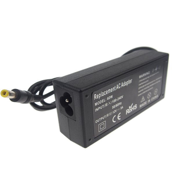
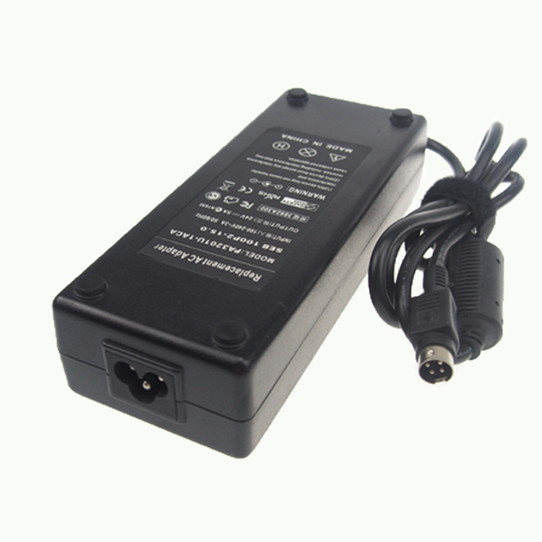
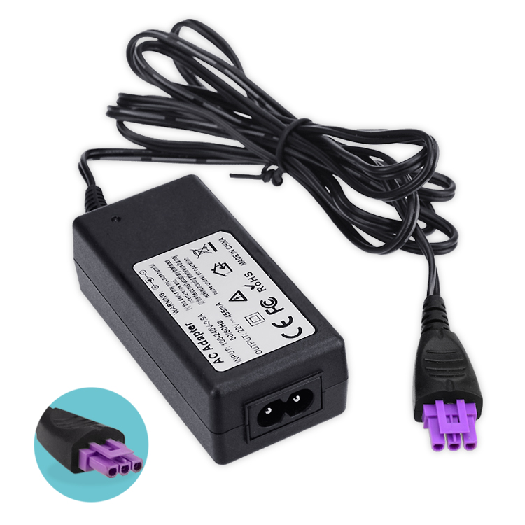
AC Adapter,Power Adapter,AC Power Adapter,Replacement AC Adapter
Shenzhen Yidashun Technology Co., Ltd. , https://www.ydsadapter.com