Coupling and Decoupling
What is a coupling capacitor, and what is a decoupling circuit?
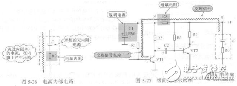
Coupling refers to the process of transferring signals from one stage of a circuit to another. Typically, this refers to AC coupling unless otherwise specified. Decoupling, on the other hand, involves filtering the power supply to minimize signal interference between stages through the power line. The coupling constant is defined as the time constant formed by the product of the coupling capacitance and the input impedance of the second stage.
Decoupling serves three main purposes:
1. Removing high-frequency ripple from the power supply and blocking high-frequency signals that may cross-talk between amplifier stages.
2. When large signals are present, the power supply may fluctuate. Decoupling helps reduce the impact of these fluctuations on sensitive stages like the input or high-gain section.
3. Creating a floating or isolated power supply to ground certain parts of the system. Decoupling capacitors also help suppress high-frequency switching noise generated by active components, directing it to ground instead of allowing it to propagate along the power lines.
This content is excerpted from Lund’s article on board-level electromagnetic compatibility design, which discusses the use of noise coupling paths, decoupling capacitors, and bypass capacitors in detail. For more information, please refer to the original paper.
Interference Coupling
Interference signals generated by a source can affect an electronic control system through various coupling paths such as wires, space, or shared power lines.
Common types of coupling include:
Direct coupling: This occurs when the interference signal directly enters the system through a wire, causing disruption. A filter or decoupling method can be used to suppress this type of interference.
Common impedance coupling: This happens when two circuits share a common path, such as a shared ground or power line. To prevent this, the coupling impedance should be minimized.
Capacitive coupling: Also known as electric field coupling, this occurs due to distributed capacitance between conductors.
Electromagnetic induction coupling: This is caused by magnetic fields interacting with the system, often requiring shielding for protection.
Radiation coupling: This happens when electromagnetic waves radiate from a source and interfere with the system. Long signal lines can act as antennas, picking up or emitting interference.
Leakage coupling: This is a form of resistive coupling, often occurring when insulation breaks down. It's important to note that while "decoupling" and "bypassing" are sometimes used interchangeably, they both serve to manage power supply noise and stabilize voltage levels.
In practical terms, decoupling and bypass capacitors are used to maintain stable power delivery, especially when load changes cause voltage fluctuations. Their roles are closely related, and the choice of capacitance value depends on the specific application and circuit requirements.
Capacitors are essential components in PCB design, and their performance significantly affects the overall quality of the board.
1. Function and Representation
A capacitor consists of two metal plates separated by an insulating material. It blocks DC but allows AC to pass, making it useful for coupling, filtering, decoupling, bypassing, and tuning. In schematics, capacitors are labeled with a "C" followed by a number, such as C8.
2. Classification of Capacitors
Capacitors are categorized based on dielectric materials (gas, liquid, solid), polarity (polar or non-polar), and structure (fixed, variable, trimmer).
3. Capacitance Value
The capacitance value determines how much energy the capacitor can store. Its reactance is inversely proportional to frequency and capacitance: XC = 1/(2Ï€fC).
4. Units and Voltage Rating
The basic unit of capacitance is farads (F), with smaller units like microfarad (μF), nanofarad (nF), and picofarad (pF) commonly used. Voltage ratings vary depending on the type of capacitor, with electrolytic capacitors typically having lower values than non-polar ones.
5. Marking and Tolerance
Capacitors are marked using direct labeling, color coding, or numerical codes. Tolerances are indicated by letters such as F (±1%), G (±2%), J (±5%), K (±10%), L (±15%), and M (±20%).
6. Polarity Identification
Polarized capacitors have a marked negative terminal, often shown as a black stripe or a longer lead. Non-polar capacitors do not require polarity consideration. A multimeter can be used to test the polarity of an unknown capacitor.
7. Practical Tips and Common Misconceptions
Some tips include using non-polar capacitors when polarity is uncertain, avoiding overloading the ripple current, and ensuring the operating voltage does not exceed the rated value. Soldering should be done carefully to avoid damaging the capacitor's housing.
Common misconceptions: Larger capacitance is not always better, as it can lead to resonance issues. Multiple small capacitors in parallel may not always improve performance. Lower ESR is not always ideal, as it can cause oscillation. High-quality capacitors do not guarantee a high-quality board—circuit design is equally important.
Pull-Up and Pull-Down Resistors
Pull-up resistors are used to ensure a stable high level at an output pin, especially when driving CMOS circuits or open-collector gates. They also help prevent floating inputs, improve noise immunity, and match impedance in long-line transmission.
Pull-down resistors function similarly but ensure a stable low level. The selection of resistor values depends on factors like power consumption, drive capability, and signal integrity. Typical values range from 1kΩ to 10kΩ.
Proper design of pull-up and pull-down resistors ensures reliable operation, minimizes interference, and optimizes performance across different circuit configurations.
- 10mL of e-liquid
- 0%/2%/3%5% nic salt by weight
- 5000 puffs per device
- 6 colors RGB Light
- Pre-filled
- Pre-charged
- OEM Available
IF like the RM similar product, you can find in R&M 1000 Puffs ,R&M BAR 9000 Puff,R&M PARADISE 10000 Puffs.
More 5000 puff Disposable Vape cand get here Elf Bar 5000 Puffs or Bang 5000 Puffs and RandM Dazzle 5000 Puffs.
Pods Disposable Vape,Vape Pen, 50000 PUFFS Vape Kit
Shenzhen Essenvape Technology Co., Ltd. , https://www.essenvape.com