Coupling and Decoupling
What is a coupling capacitor, and what is a decoupling circuit?
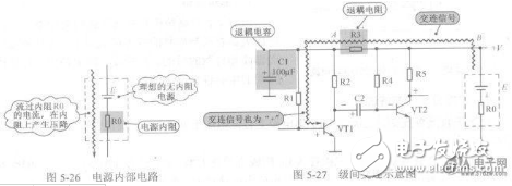
Coupling refers to the transmission of signals from one stage to another in an electronic system. In most cases, this implies AC coupling unless otherwise specified. On the other hand, decoupling involves filtering the power supply to reduce interference between stages via the power lines. The coupling constant represents the time constant formed by the product of the coupling capacitance and the input impedance of the next stage.
Decoupling serves three main purposes:
1. Removing high-frequency ripple from the power supply and blocking high-frequency signals that may cross-talk through the power line.
2. When large signals are present, the power supply can fluctuate, and decoupling helps minimize the impact of these fluctuations on sensitive stages like the input or high-gain section.
3. Creating a floating or isolated power supply, allowing certain parts of the system to be grounded or powered independently. This is especially useful in complex systems where noise generated by active components must be contained. Decoupling capacitors provide a local DC path, reducing noise propagation and directing it to ground.
Excerpted from Lund’s “Board-Level Electromagnetic Compatibility Design,†this article provides a comprehensive explanation of noise coupling paths, decoupling capacitors, and bypass capacitors. For more details, refer to the original source.
Interference Coupling
Interference signals from a source can affect the performance of an electronic control system through various coupling channels, such as wires, space, or shared power lines. Common types of interference include direct coupling, common impedance coupling, capacitive coupling, electromagnetic induction coupling, radiation coupling, and leakage coupling.
Direct coupling occurs when interference directly enters the system through a wire, and can be suppressed using filters or decoupling techniques. Common impedance coupling happens when two circuits share a common path, which can be mitigated by minimizing shared impedance. Capacitive coupling results from distributed capacitance, while electromagnetic induction coupling arises from magnetic fields. Radiation coupling comes from electromagnetic waves, often affecting long signal lines. Leakage coupling is due to resistive paths, typically occurring when insulation degrades.
In terms of terminology, "decoupling" and "bypass" are often used interchangeably, though their application depends on the context. Both serve to manage power supply noise caused by load variations. While there may be differences in capacitance values, the key is to match the design requirements for stability and noise reduction.
Capacitors are essential components in PCB design, playing critical roles in coupling, filtering, decoupling, and signal tuning. They are represented in circuits with a letter 'C' followed by a number, such as C8. Capacitors can be classified based on dielectric material, polarity, and structure. Their capacitance determines energy storage capacity, and the reactance (XC) is calculated as 1/(2Ï€fC), where f is frequency and C is capacitance.
Capacitance units include farads (F), microfarads (μF), nanofarads (nF), and picofarads (pF). Each capacitor has a rated voltage, with electrolytic capacitors having lower voltages compared to non-polar ones. Marking methods vary, including direct labeling, color coding, and numerical codes. Capacitor tolerances are indicated by symbols such as F, G, J, K, L, and M, representing ±1%, ±2%, ±5%, ±10%, ±15%, and ±20% respectively.
Identifying the polarity of a capacitor is crucial, especially for electrolytic types. The negative terminal is usually marked, and the pin length or multimeter testing can help determine it. Proper handling during soldering is also important to avoid damaging the capacitor.
When using capacitors, several common misconceptions should be avoided. Larger capacitance isn’t always better, as it may introduce parasitic inductance and resonance issues. Parallel small capacitors may not significantly reduce ESR (equivalent series resistance), and low ESR doesn't always improve performance, as it can cause oscillation. Lastly, high-quality capacitors alone don't guarantee better board performance—circuit design and component selection are equally important.
Pull-Up and Pull-Down Resistors
Pull-up resistors are used to ensure a defined logic level when a signal line is inactive. They are commonly used in TTL-to-CMOS interfacing, open-collector (OC) gates, and to increase drive capability. Pull-up resistors also prevent static damage to unused CMOS pins and improve noise immunity.
Similarly, pull-down resistors provide a stable low-level signal when no active device is driving the line. The selection of resistor values balances power consumption and drive capability, typically ranging between 1kΩ and 10kΩ. Factors such as switching speed, threshold levels, and RC delay must also be considered.
In summary, understanding coupling, decoupling, and resistor usage is fundamental in designing reliable and noise-resistant electronic systems. Proper component selection and layout practices are essential for achieving optimal performance and stability.
Waspe Vape Disposable,Best Disposable Vape Waspe In Germany,Best Disposable Vape WASPE Tornado 15000 PUFF
Shenzhen Essenvape Technology Co., Ltd. , https://www.essenvape.com