**1. Introduction**
The development and application of single-chip microcontrollers have become deeply embedded in various aspects of daily life. One of the key applications is mass programming of chips with limited memory, where a high-speed programmer with stable performance is essential for large-scale chip burning by major manufacturers. Currently, the most commonly used programmer in the market is based on the 89C51 microcontroller. However, its limited functionality struggles to meet the growing demands of the market. This paper presents a new programmer that utilizes the MSP430F149 microcontroller as the central control unit. Compared to traditional 51 MCU programmers, this design introduces an I2C memory module, enabling standalone chip programming without the need for a computer. This enhancement not only improves convenience but also significantly increases the speed of the programming process.
**2. System Design**
The MSP430-based programmer is built around the MSP430F149 microcontroller and consists of several key components: a keyboard, display, serial port, programming interface, level shifting circuit, power supply, and storage module. The overall system architecture is illustrated in Figure 1.

Figure 1: System Block Diagram
**3. Hardware Circuit Design** **3.1 CPU Module** The core of the programmer uses the ultra-low-power MSP430F149 microcontroller [1]. Figure 2 shows the schematic of the minimum system for the MSP430F149. Y1 and Y2 are crystal oscillator modules, RST is connected to the reset circuit, P1 is the data transmission port, P3.0–P3.4 provides the upper 4-bit address output, P4 provides the lower 8-bit address output, P5.3 and P5.4 are connected to the keyboard, P2 and P5.0–P5.2 are linked to the LCD display, and P3.6 and P3.7 connect to the memory module.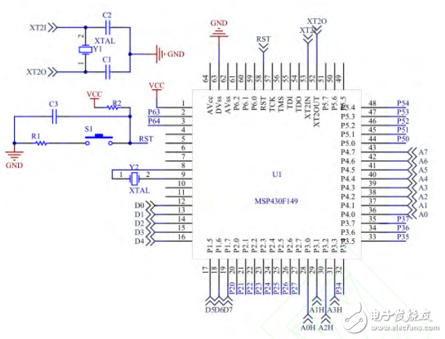
Figure 2: Schematic of the Minimum System of the MSP430F149
**3.2 Serial Port Module** Since the signal levels of the MSP430F149 differ from those of the host computer, a level-shifting circuit using the MAX232 is implemented. The MAX232 is a standard RS-232 interface chip that operates on a single +5V power supply. It facilitates communication between the microcontroller and the host computer. **3.3 Storage Module** As shown in Figure 3, the storage module includes an I2C-based EEPROM, specifically the AT24C16 chip, which has 8 KB of memory. The SDA and SCL lines connect the MSP430F149 to the AT24C16, allowing the programmer to store the firmware to be programmed onto the 51 MCU, thus supporting offline operations.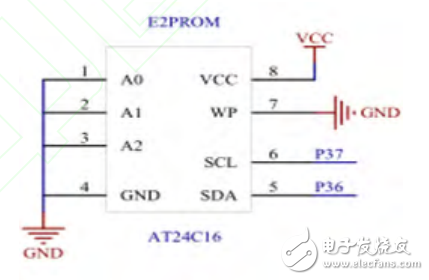
Figure 3: Connection Diagram of the Storage Module
**3.4 Keyboard and Display Module** The keyboard module uses a PS/2 interface, known for its reliability and simplicity, requiring only two signal lines. It is primarily used for function selection during the programming process. Figure 4 illustrates the connection diagram of the keyboard module.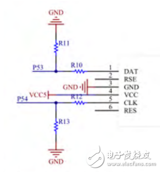
Figure 4: Schematic of the Keyboard Module Circuit
The display module uses a 1602 LCD to show relevant parameters such as the chip type, programming voltage, and functions like read, write, and erase. Figure 5 shows the circuit connection of the display module. The MSP430F149 controls the display based on commands from the keyboard, providing real-time feedback on the programmer’s status and data.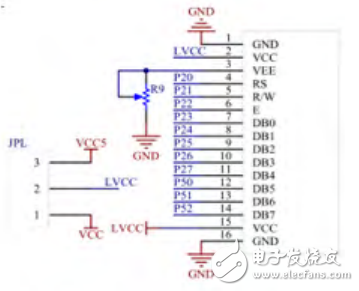
Figure 5: Schematic of the Display Module Circuit
Differential Mode Inductors,I type Inductors,Common Mode Inductors,Differential Mode Choke Inductor
Xuzhou Jiuli Electronics Co., Ltd , https://www.xzjiulielectronic.com