1. Foreword In recent years, with the rapid development of the national economy and the improvement of people's living standards, the number of various motor vehicles has increased sharply, and the number of car navigation systems has also increased dramatically. This article uses an embedded system based on the ARM9-Linux platform as the system's control platform to improve the system's performance, integration, and scalability; using a combination of GPS positioning technology and advanced GPRS wireless communication technology to achieve vehicle electronics Map navigation and short message alarm; through the design of the LCD module, the flexible display of various vehicle information is realized, which enriches the human-computer interaction interface and makes the system more intelligent. The vehicle-mounted GPS navigation system studied in this paper is an important branch of Intelligent Transport System (ITS), which is of great significance for solving urban transportation problems.
2. GPS Global Positioning System (1)
The GPS (Global PosiTIoning System) system includes three parts: the space part—satellite constellation, the ground control part—the ground monitoring system, and the user equipment part—the signal receiver. GPS Global Positioning System is a high-precision, all-weather and global radio navigation positioning and timing multi-function system established with the development of modern science and technology. It uses a satellite network consisting of 24 artificial satellites located more than 20,000 kilometers away from the earth to continuously send positioning signals to the earth. Any GPS receiver on the earth, as long as it receives any more than four satellite signals, after calculation, you can get the GPS receiver's position (longitude, latitude, altitude), time and motion status and other information. The GPS system has the characteristics of high precision, all-weather, high efficiency, multi-function, easy operation and wide application.
3. The overall system design system mainly implements car navigation and vehicle anti-theft functions based on mobile phones. The whole system includes two parts: one is the owner's mobile phone, and the other is the vehicle-mounted part. The mobile phone part is just a mobile phone, used to send and receive short messages. The vehicle-mounted part mainly realizes the positioning and navigation function of the vehicle volume. The vehicle-mounted part has two working modes: the first is the "driving mode". In this mode, the owner drives the car by himself. The owner can conveniently use the man-machine interface of the car navigation system to navigate; when the owner needs to leave his car Press the "Safe Mode" button to start the second working mode. After starting this mode, the system continuously uses GPS positioning technology to determine whether the vehicle's current position has changed. If someone steals the car and the car's position changes after driving the car, and the system finds that the latitude and longitude of the car's position changes, the system will send a short message to the car owner in real time to report the car's current location through the GPRS network.
4. System hardware design The hardware of this system is mainly composed of two parts: main control module and expansion module. The expansion module mainly includes GPS module, LCD module and GPRS module. The structural block diagram of the system hardware is shown in Figure 1: 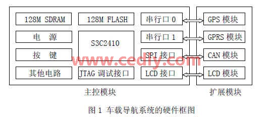
4.1 Design of main control module (2)
The design of the main control module is the core of the hardware design, which mainly includes the design of the power circuit, clock circuit, reset circuit, memory module circuit, JTAG interface circuit, serial port circuit, LCD interface, SPI interface and key circuit. The processor in this article uses Samsung's S3C2410, and the main control module is connected to the expansion module through the serial port, SPI interface, and LCD interface to form the entire hardware system.
4.2 GPS module selection
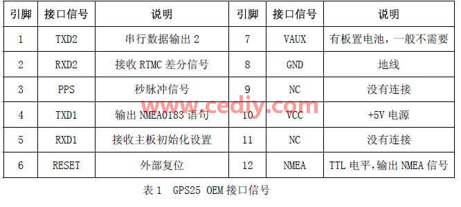
The GPS module mainly completes the reception and processing of GPS positioning information. The GPS25-LVC receiver of GARMIN is selected. GPS25 OEM interface signals are shown in Table 1:
4.3 GPRS module selection
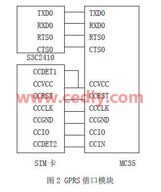
The GPRS module can be used for wireless communication, including voice communication, sending and receiving short messages, and wireless Internet access. This system selects MC35 and mainly uses it to complete the short message function. The hardware connection is shown in Figure 2:
5. Software design The hardware of the car navigation system lays a solid foundation for the realization of basic functions and extended functions. The design of the software system is to make full use of the resources provided by the hardware platform and realize the orderly operation of business processes. It is important for the design of the entire system component. The design of the software part mainly includes (3):
(1) Establish cross-compilation environment; (2) Bootloader transplantation; (3) Linux operating system including driver transplantation; (4) GPS positioning module programming; (5) GPRS communication module programming; (6) display interface design , This article implements the design of the above interface based on MiniGUI;
5.1 GPS module software design
The GPS module mainly completes the collection, processing and storage of vehicle position information. Because GPS uses serial port communication, this paper realizes the reception, processing and storage of GPS data on the basis of serial port communication. The basic idea of ​​the software design of the module is this: first receive the complete NMEA0183 sentence, then extract the relevant data, such as time, latitude, longitude, speed, etc., and then send these data to display or send out, and save it for future review.
In this paper, the NMEA0183 sentence output by GPS25-LVC serial port 1 is selected. The format is as follows: $ GPRMC, 082 004, A, 3990.347 2, N, 11 953.099 0 E, 000.0, 000.0 130 807 002.5, W * 71, indicating that the current time is 8:20:04 on August 13, 2007 ( This is UTC time, not local time, the difference between the two is about 8 hours), the position is 39 degrees north latitude 90.347 2 minutes, longitude 119 degrees 53.099 0 minutes, the speed is O.
5.2 Software design of GPRS wireless communication module In the software control of MC35 module, the standard V.25 ter AT command is mainly used. The relevant AT commands used in system development are shown in Table 2 (4).


The specific execution process of the AT command is as follows:
AT
OK
AT + CSCA = +8613800773500 \ r
OK
AT + CMGF = 1 \ r
OK
AT + CMGS = + 861348137… \ r
> Your car is being stolen! \ X1A
+ CMGS: 206
OK
When running the alarm function, after the above steps are executed, an alarm short message will be sent out, and the owner's mobile phone will receive a text message with the content "Your car is being stolen!". Then, the MC35 module reads the current geographic location in real time in the corresponding storage area under the control of the MCU, and continuously reports it to the owner in the form of a short message to help the owner and the police pursue the vehicle.
5.3 Software design of interface display (5)
The development of embedded applications is completed on the host machine (such as a PC), debug and run the embedded application on the host machine, and then compile and link the embedded application into binary target code that can run on the target platform. Since the MiniGUI library is used, the MiniGUI library must be compiled and linked into a binary object code library that can be run on the target platform. When a MiniGUI application is deployed on the target platform and runs reliably, the development process ends. The positioning information interface displays the position and other information of the vehicle received through GPS, and then expands the electronic map to display the information more intuitively. Figure 3 describes the
MiniGUI software development process: 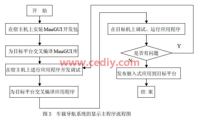
6. Summarize the author's innovations in this article: 1) The vehicle navigation function is designed and implemented on the ARM-Linux platform. The system has the characteristics of low cost, low power consumption, high processing performance and good stability. 2) This platform facilitates system hardware and software upgrades.
High brightness, the light source is made of imported ultra-high brightness LED series, 120LED / m or 144LED / m encryption arrangement is the fundamental guarantee of the overall luminous effect and high brightness.
DIP & SMD LED lamps are options for different application.
Baiyang LED flex neon sign is widely used in shop,restaurant,home decoration,events as image wall,window sign,directional sign,brand logo,door head and gifts.send us the artwork and dimension.you are ensured to enjoy the unique private custom experience
Neon Letters,Led Alphabet Letters,Led Light Up Letters,Custom Led Letters
Shenzhen Oleda Technology Co.,Ltd , https://www.baiyangsign.com