Grounding classification of communication equipment
In communication equipment and communication systems, various circuits have potential references. Connect all the reference points together through a conductor. This conductor is the ground wire inside the communication device or system. If these reference points are connected to a conductor plane , Then the plane is called the reference plane, and all signals use this plane as the zero potential reference point. Communication equipment often uses its metal base, shell or copper strip as a reference surface. The reference surface is not necessarily connected to the ground. Under normal circumstances, the reference surface is connected to the ground for two purposes: one is for the device The operator provides safety guarantee; the second is to improve the working stability of the equipment.
a. Working grounding The working grounding of communication equipment is mainly to make the entire electronic circuit have a common zero-potential reference plane, and provide a low-impedance path for high-frequency interference signals, as well as to enable shielding measures to play a good effect. There are three main ways to work grounding.
(1) Floating ground Floating ground means that the ground wire of communication equipment is electrically insulated from the building grounding system. As shown in Figure 1-1, the insulation resistance between the two should generally be above 50MΩ, so that the building is grounded The electromagnetic interference in the system cannot be transmitted to the communication equipment, and the change of the ground potential has no effect on the equipment. In many cases, in order to prevent the interference current on the casing of the electronic device from directly coupling to the electronic circuit, the casing is often grounded, and the electronic circuit therein is floating. The advantage of the floating method is that it has strong anti-interference ability. The disadvantage is that it is easy to generate static electricity. When the lightning induction is strong, a high voltage may appear between the casing and the internal electronic circuit, which will break the insulation gap between the two. Damage to electronic circuits. 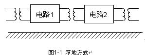
(2) Single-point grounding takes a certain point in the entire communication system as the grounding reference point, and the signal ground of each unit is connected to this point, as shown in Figure 1-2, the figure (a) is a series single-point grounding , Figure (b) is a single point of parallel grounding. Single-point grounding can avoid the formation of ground loops and prevent current propagation interference through ground loops. Under normal circumstances, separate low-amplitude and susceptible small-signal circuits (such as preamplifiers, etc.) from a single ground wire and other circuits. Large-signal circuits with large amplitude and power (such as final-stage amplifiers and high-power circuits, etc.) have large operating currents, and the current flowing through the ground wire is large. Has its own ground wire. When multiple power supplies are used for power supply, each power supply should have its own ground wire, and these ground wires are directly connected to a point to ground. 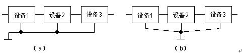
Figure 1-2 Single-point grounding method In many buildings, there is a certain distance between the installation location of electronic equipment and the indoor grounding bus. The use of this single-point grounding tends to make the grounding wire have a longer length, because Each ground wire has an impedance. When the frequency of the current flowing through the ground wire is high enough, its wavelength will be comparable to the length of the ground wire. At this time, the ground wire should be regarded as a distributed parameter transmission line. If the length of the ground wire reaches 1 At an odd multiple of / 4 the current wavelength, the input impedance of the ground wire tends to infinity, which is equivalent to an open circuit. Therefore, single-point grounding is generally only suitable for low-frequency circuits below 0.1MHz.
(3) Multi-point grounding Connect the grounding points of each device in the communication system directly to the ground plane closest to them, as shown in Figure 1-3, so that the length of the grounding wire can be minimized. The ground plane mentioned here refers to the metal (with high conductivity) band that runs through the entire communication system, which can be the bottom plate and structural frame of the device, or it can be an indoor ground bus or ground grid. 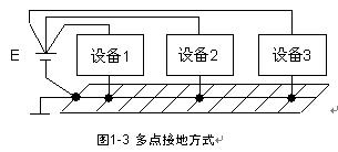
The prominent advantage of using multi-point grounding is that it can be grounded nearby. Compared with single-point grounding, it can shorten the length of the ground connection and reduce its parasitic inductance, which is beneficial to lightning protection. However, after using multi-point grounding, a lot of ground loops may be generated inside the device or system. Large-signal circuits can affect small-signal circuits through ground loop currents, causing interference, and sometimes the electronic circuits may not work properly. When this happens, you can use a mixed grounding method. For high-frequency circuits with signal frequencies above 10MHz, use multi-point grounding, for low-frequency circuits with signal frequencies below 0.1MHz, use single-point grounding, and for those signal frequencies at For circuits between 0.1MHz and 10MHz, if the actual ground connection length does not exceed 1/20 of the signal wavelength, single-point grounding can be used; otherwise, multi-point grounding should be used.
b. Safety grounding When a lightning strike occurs, a strong lightning transient current flowing through the grounding system of the building will cause the transient ground potential to rise, endangering the safety of equipment and people. Generally, when using electronic equipment, it is often accompanied by strong electrical equipment such as power supply. Both the communication equipment and the strong electrical equipment need to be grounded, but it is often very difficult to separate the grounding of the communication equipment and the strong electrical equipment from each other. In buildings, it is relatively easy to share a grounding system between communication equipment and high-power equipment, but this common ground also brings some side effects. The communication equipment and the strong electric equipment share the ground. When the lightning strikes, the transient large current can interfere with the electronic equipment or generate overvoltage through the coupling of the circuit. In addition, the transient high potential caused by the lightning transient current flowing through the grounding system can also pass. Various power lines, signal lines and metal pipes propagate far away from the grounding system and were originally zero potential, which will pose a safety threat to the communication equipment and operators here. In order to overcome these side effects, communication equipment and strong electrical equipment are separately grounded in some places, and many complex isolation and insulation measures are adopted to lead the grounding wire of the electronic equipment to a place far away from the strong electrical equipment grounding system (20m away). Grounding, in fact, this kind of separate grounding is not easy to achieve. Due to the crisscrossing of steel lines in various lines, metal pipelines and building frameworks and the continuous expansion of some buildings, a slight omission in design and construction is likely to cause transient high potentials appearing in the strong electrical equipment area to pass through metal pipelines or frameworks Reinforcing steel bars lead to the low-potential communication equipment area, or lead the low-potential of the communication equipment area to the strong electric equipment area, which may cause breakdown discharge and endanger the safety of equipment and people. Some manufacturers require their computers to be grounded separately, that is, the computer's grounding wire is led to a certain distance outside the building and then connected to a separate ground network. Such grounding requirements are often impractical. When the building is struck by lightning, the ground potential of the building will rise instantaneously. Since the computer ground is separated from the ground network of the building, the computer ground line will still maintain a low potential at this time, so it is easy to cause breakdown discharge to the computer To damage the computer. For this reason, a low-voltage surge arrester or discharge gap can be used to discharge the grounding wire of the computer to the home, so that the computer ground and the building grounding network reach approximately the same potential level, which is called transient common ground. Under normal circumstances, a lightning arrester or a discharge gap separates the two grounds, which is beneficial to anti-interference, and when lightning strikes, the equalization between the two can be achieved to avoid breakdown discharge and endanger the safety of the equipment. From the perspective of lightning transient overvoltage suppression, the use of this transient common ground and the use of voltage equalization measures can lift the building and its internal strong electrical equipment, electronic equipment, and operators at the same time when a lightning strike occurs High to approximately equal potential level, so that there is no transient potential difference between equipment and equipment and between equipment and people.
In fact, using a longer lead wire to pull to a farther place to ground alone, in the case of low-frequency signals, it is also meaningful to protect the equipotential of the electronic equipment and the separate grounding point in the distance, but in the case of high-frequency signals, it is more The impedance of the long lead will affect the effect of equipotentiality, especially when the relationship between the signal wavelength and the length of the lead meets an odd multiple of 1/4, the lead is equivalent to an open circuit, which does not play the role of extended ground.
Eight Blades Ceiling Fan
Large Ceiling Fan,Eight Blades Ceiling Fan,8 Blades Ceiling Fan,8 Blade Large Size Ceiling Fan
Jiangmen MagicPower Electrical Appliances Co.,Ltd. , https://www.magicpowerfan.com