Automobile meters are a window for information exchange between cars and drivers, and they are also the main part of high-tech automotive technologies. Countries have been working hard to develop automotive meter technologies and have continuously made new progress. Automobile meters are gradually developing in the direction of digitization and intelligence. Using digital virtual meters to replace electrical or electronic meters commonly used in China at this stage has become an important issue in vehicle automation. The virtual digital automobile instrument information system independently developed by the author has been successfully installed on the Aspire pure electric concept car developed by the School of Automotive Engineering of Wuhan University of Technology for actual vehicle testing, and on this basis, the vehicle's positioning, navigation and rear view Functions such as photography, network communication, audio-visual entertainment, and car black box. This sample car is an application example of virtual digital automobile instrument. This paper gives the hardware composition, human-machine interface and software implementation of LabVIEW based on the virtual digital automobile instrument information system.
1. The key technology of virtual digital automobile instrument information system
Virtual digital automobile instrument information system is an intelligent system that integrates various automotive electronic technologies, including intelligent instrument system, vehicle navigation system, fault diagnosis system and vehicle black box subsystem, etc., which is the hotspot of automobile industry in various countries.
(1) Data collection technology
In addition to data such as gyroscopes and odometers for navigation, the collected car data also needs to collect data reflecting car performance parameters such as car spindle speed, tire pressure, and temperature in order for the driver to understand the status of the vehicle. The methods that can be used for the car data acquisition module depend on the actual situation.
(2) GSM communication technology
To realize the intelligence of the vehicle, a network communication function must be established on the vehicle. The choice of communication network is the key, it determines the system's capacity, reliability and coverage of information center monitoring coverage. The realization of communication technology can realize vehicle wireless communication, mobile office and Internet surfing.
(3) Data dump module
The status information, location information, speed information and load of each major equipment of the car are important information to determine the cause of the accident. It is necessary to save the historical data before parking. To facilitate the output of the data, a non-contact IC card or mobile hard disk USB is used. Storing data. This is the function of the car black box.
(4) Display technology of virtual digital meters
The amount of information of the virtual digital instrument is very large. For example, the display method of the traditional instrument will increase the number of in-vehicle instruments, which will make the vehicle dashboard appear crowded and increase the difficulty of the driver ’s operation. attention. Vehicle-mounted virtual digital instruments built with virtual instrument technology solve these problems. It integrates all the information display on a screen and displays it in a split interface method, which will make it very convenient for the driver to view the information, eliminate many instruments, and make the interior space of the car more spacious, comfortable and beautiful.
2. The hardware composition and human-machine interface of the virtual digital automobile instrument information system
(1) Hardware composition of virtual digital automobile instrument information system
The principles of selection and combination of system hardware are: fully consider the compatibility and cost performance of each hardware; fully consider the electromagnetic compatibility of the system to ensure that the system can work normally in a relatively harsh electromagnetic environment; meet the basic functional requirements of the system, and fully consider The expandability and simplicity of the system reserve several expandable interfaces.
The information system is composed of PC, peripheral hardware equipment, operating system and user's application program. Peripheral hardware equipment is mainly composed of LCD display, touch screen, digital I / 0 data acquisition card, wheel speed sensor, battery monitoring system, CCD camera, TV card, GPS receiver and wireless Internet card, etc. Virtual digital automobile instrument hardware system structure As shown in Figure 1. 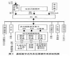
(2) Human-machine interface of virtual digital automobile instrument information system
The virtual digital automobile instrument information system integrates virtual technology and digital technology, and has multiple functions such as virtual instrument, electronic rearview mirror, fault monitoring, operation record, GPS vehicle positioning, multimedia audio and video, Internet communication and mobile office. The functional interface is shown in Figure 2.
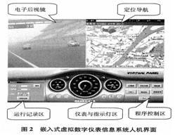
1. Instrument and indicator area
The instrument and indicator area displays the speedometer, battery charge status meter, battery temperature meter, lighting and signal indicator, alarm signal indicator and gear indicator. When the vehicle speed exceeds a certain speed limit, an overspeed voice prompt will be issued. 2. Operation record area
The operation record area displays a one-way odometer with reset button, cumulative odometer, date and time and operation record button. The one-way odometer shows the mileage of a single trip. Press the reset button to return the one-way odometer to zero; the cumulative odometer shows the cumulative total mileage of the car; press the operation record button to display the speed, mileage, fault and running Alarm history (car black box function).
3. Program control area
The program control area displays the following buttons for running the program: electronic rear view environment, in-vehicle positioning and navigation, Internet browser, MP3 player, wireless TV and FM radio.
4. Electronic Rear View Zone
The electronic rear view area displays the rear image of the car taken by the camera to facilitate the driver to observe the traffic situation behind the car.
5. Positioning navigation
The positioning navigation area displays an electronic map, which uses the car positioning information received by the GPS receiver to depict the running track of the car on the electronic map. The positioning navigation program can provide a static navigation function, and can determine the shortest driving route according to the names of the start and end points provided by the driver.
3. Software implementation of virtual digital automobile instrument information system
In addition to the need for a stable and high-performance hardware platform for the performance of the entire system, software plays a vital role. The various functions and combinations of the system, the manifestation of the human-machine interface, etc. are all done through software.
This system uses LabVIEW, an intuitive graphical programming language, to establish a front panel human-machine interface and program block diagram in a very intuitive way to complete the programming process. The front panel can be seen by users, similar to the operation panel of traditional instruments, using the tool template to add input controllers and output indicators from the control template, and the types of controllers and indicators can be selected. The block diagram is the core that supports the virtual instrument to realize its function. The design of the block diagram involves the design of nodes, data ports and wiring. Connections represent data trends, and nodes are functions, VI subroutines, structures, or code interfaces.
The overall flow chart of the software design of the virtual digital automobile instrument information system is shown in Figure 3.
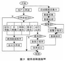
The content of the virtual digital automobile instrument information system is very rich. In order to make the interface of the instrument clear, beautiful and comfortable, the content of the vehicle information system is divided into different interface displays according to the characteristics of the displayed information and the frequency of the driver's needs.
The display operation of the virtual digital automobile instrument interface is realized through the touch screen. By touching the soft button of the corresponding function on the main interface with your finger, you can switch to the interface you want to view. The interface display of the virtual digital automobile instrument information system is shown in Figure 2. The realization of the specific functions of the virtual digital car instrumentation is completed by software. The software mainly completes the following functions. 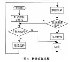
(1) Drive and initialize each function board in the computer
1. Data acquisition card driver
Various types of data acquisition cards produced by NI are very convenient to use. Before writing the VI, you only need to set the relevant parameters under the "Measurement & AutomaTIon" driver software in LabVIEW.
2. Initial setting of data acquisition parameters
In order for the data acquisition card to correctly implement the data acquisition function, some parameters must be set according to the actual measurement needs. The parameters to be set mainly include the device number and address code of the acquisition card, in addition to the setting items of the analog signal input part, the setting items of the A / D conversion part, the setting items of the D / A conversion part, and the settings of the DIO and counter parts item.
(2) Convert and process various sensor signals
Data acquisition and processing: The analog voltage signal or pulse signal and switching value signal converted by the sensor are collected to the corresponding channel of the data acquisition card, and digital filtering, format conversion, equivalent operation and unit conversion are performed, and the data is converted into The data shown on the display.
The data processing part is relatively simple, and data acquisition is the key to software programming. The signals of data acquisition are analog, digital switch, and pulse digital. The overall flow of data acquisition is shown in Figure 4. (3) Realization of positioning and navigation
1. Drivers for positioning and navigation
Since the navigation module is an outsourced integrated board, the manufacturer provides driver function libraries written in C, C ++, and BASIC. How to call it in the LabVIEW environment is a problem that needs to be solved when using outsourced products.
LabVIEW has several solutions to this type of problem, such as direct port I / O, calling CLF nodes, and calling CIN nodes. The CIN method is used here. CIN is a general method for calling C source code in LabVIEW. C language is currently recognized as a more powerful programming language. LabVIEW can greatly expand its overall functions by interfacing with C language.
CIN is a function node located in the LabVIEW block diagram program window. On the function template Advanced sub-template, C language source code can be introduced into LabVIEW. The user can compile the external code to be called into a format recognized by LabVIEW and connect it to this node. When this node executes, LabVIEW will automatically call the external code connected to this node and pass a specific data structure to CIN. Because the storage format of data in LabVIEW follows the storage format of data in C language, and the two are completely the same, using CIN can obtain higher program efficiency. The CIN node needs to call the file in .lsb format. Using the CINTools built-in tool of LabVIEW, the Visual C ++ source code can be compiled into the .lsb format recognized by the CIN node.
The driving methods of other purchased modules (camera, communication card, TV card, etc.) are all carried out in this way.
2. Positioning and navigation interface
When the GPS device is purchased, the electronic map software is attached. After installing and linking with LabVIEW, click the navigation soft key in the main interface of the virtual digital automobile instrument information system to call the GPS navigation interface.
(4) Realization of rearview camera and network communication
The rear-view camera and network communication module are outsourced modules. The outsourced module manufacturers all provide C source code drivers. The work we do only needs to call it in the LabVIEW environment and link the software.
(5) Realization of audiovisual entertainment
The audiovisual entertainment part includes TV and MP3. Among them, the TV is an outsourced TV module, and its implementation method is similar to that of positioning and navigation driving, while MP3 is realized by calling the playback software.
(6) Realization of the function of automobile black box
This virtual digital automobile instrument realizes the function of the car driving recorder-black box through software, which is also the advantage of this system compared with the traditional instrument system.
The black box of the car needs to record data such as the vehicle's motion status, the key safety component's motion status, and the driver's operating behavior during the last period of a dangerous accident. In the accident handling stage, this information will be used to partially or fully reproduce the process of the accident, analyze and determine the cause of the accident, which requires data storage and query. The virtual instrument software designed with LabVIEW can realize the functions of data storage and data query.
Data storage: Save the sampling data to a file, which can be saved as a text file or a spreadsheet file, or as a file in the form of dynamic data recording unique to LabVIEW. The file of dynamic data recording can only be opened in this system.
Data query: read the previously saved data record file.
4. Conclusion
The virtual digital instrument has undergone many actual vehicle tests to prove that this system is safe and reliable, and the display data can meet the actual driving needs in terms of accuracy.
In summary, the application of the virtual digital car instrumentation makes the meter reading clearer and more intuitive, more information, more intelligent, low power consumption and short development cycle, which is relatively large in cost compared to traditional vehicle equipment Advantage, so it has broad application prospects. Of course, this field is still in its infancy in China, and there is still a lot of work to be done in order to become a truly practical stage, but as the technology matures, it will have a profound impact on the automotive industry.
I-Pulse Feeder , original and new or used one, in stock, high quality.
Material: Stainless steel
Feeder can be divided into tape feeder, tube feeder, tray feeder or stick feeder.
Feeder can be divided into original feeder and replacement feeder.
All the feeders shall be maintained during the use time
In addition, the following spare parts will be sold in our company.
SAMSUNG Feeder
Panasonic Smt Feeder
Panasonic Feeder
Smt Machine Panasonic Feeder
SMT Feeder For Panasonic
JUKI Feeder
I-pulse Feeder
I-Pulse Feeder
I-Pulse Feeder,Smt I-Pulse Feeder,Smt Parts I-Pulse Feeder,I-Pulse Type Feeder
Shenzhen Srisung Technology Co.,Limited , https://www.sr-smt.com