In general, we use a buck-boost topology to solve the wide input voltage range and cold start requirements in automotive applications. This article will explain the cold start requirements in detail and introduce two different solutions. One of them is the traditional SPEIC topology, and the other is the newer multi-switch buck / boost topology.
The advantages and disadvantages of each scheme will be explained below, and the advantages of the dual-switch buck / boost topology over the traditional SEPIC topology will be highlighted. In addition, this article will also combine with the latest LM5118 current mode buck / boost controller from National Semiconductor for application description.
Cold start conditions
Starting a car actually drives the internal combustion engine through an electric starter motor. The power consumption of the electric starter motor is provided by the car battery. The large load required to start the motor will cause the battery voltage to gradually decrease. For car starting, the worst case is "cold start". This situation occurs in an environment with extremely low temperature, and the low temperature environment will make the cold start of the car more difficult. When the car is in an extremely low temperature environment, the internal combustion engine's rotational resistance will rise to the highest, so it requires a large mechanical force to start. Therefore, the peak current consumed by the electric starter motor will be higher than when it is started in a warm environment. Another influencing factor in the case of "cold start" is that the voltage of the car battery will drop as the temperature drops, and the older the battery, the greater the drop.
The above two low temperature effects will cause the minimum supply voltage of the car battery to drop significantly. The ISO7637 standard stipulates the basic voltage waveform of automobiles under cold start conditions. Figure 1 shows the voltage characteristics under cold start conditions, which generally define the voltage as two voltage levels. First, when the electric starter motor begins to rotate to overcome the initial mechanical resistance, the supply voltage is at its lowest. Then the mechanical system runs and the required voltage increases accordingly. Finally, when the electric starter motor is turned off, the system voltage will return to normal levels. 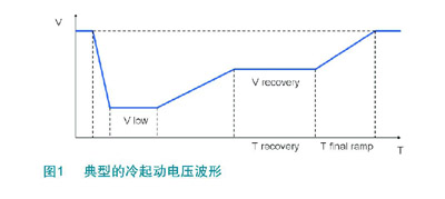
In general, we use a buck-boost topology to solve the wide input voltage range and cold start requirements in automotive applications. This article will explain the cold start requirements in detail and introduce two different solutions. One of them is the traditional SPEIC topology, and the other is the newer multi-switch buck / boost topology.
The advantages and disadvantages of each scheme will be explained below, and the advantages of the dual-switch buck / boost topology over the traditional SEPIC topology will be highlighted. In addition, this article will also combine with the latest LM5118 current mode buck / boost controller from National Semiconductor for application description.
Cold start conditions
Starting a car actually drives the internal combustion engine through an electric starter motor. The power consumption of the electric starter motor is provided by the car battery. The large load required to start the motor will cause the battery voltage to gradually decrease. For car starting, the worst case is "cold start". This situation occurs in an environment with extremely low temperature, and the low temperature environment will make the cold start of the car more difficult. When the car is in an extremely low temperature environment, the internal combustion engine's rotational resistance will rise to the highest, so it requires a large mechanical force to start. Therefore, the peak current consumed by the electric starter motor will be higher than when it is started in a warm environment. Another influencing factor in the case of "cold start" is that the voltage of the car battery will drop as the temperature drops, and the older the battery, the greater the drop.
The above two low temperature effects will cause the minimum supply voltage of the car battery to drop significantly. The ISO7637 standard stipulates the basic voltage waveform of automobiles under cold start conditions. Figure 1 shows the voltage characteristics under cold start conditions, which generally define the voltage as two voltage levels. First, when the electric starter motor begins to rotate to overcome the initial mechanical resistance, the supply voltage is at its lowest. Then the mechanical system runs and the required voltage increases accordingly. Finally, when the electric starter motor is turned off, the system voltage will return to normal levels.
In order to provide highly accurate output voltage regulation over a wide input voltage range, two switching MOSFETs must be driven with appropriate control methods to provide a smooth transition between buck and buck / boost modes. The controller can operate in three different modes according to the input and output conditions:
1. Buck operation Vin> Vout: If Vin is greater than Vout by a sufficient amount, the regulator will operate in the form of a traditional buck regulator. In this mode, the buck conversion function is Vout / Vin = D, where D is the duty cycle of Q1, and the simple buck operation mode can ensure the best efficiency and regulation effect.
When Vin falls below Vout to a duty cycle close to 70%, the boost switch will be activated with a minimum duty cycle, causing the regulator to enter a soft buck / boost mode (Figure 3a).
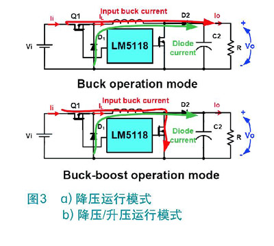
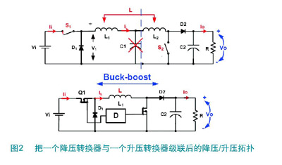
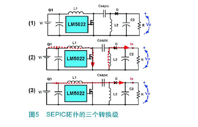
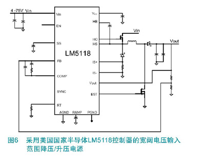
2. Buck / boost operation Vin≈Vout: As Vin further decreases to approach Vout, the duty cycle of the buck switch will decrease, while the duty cycle of the boost switch will increase. This also allows the buck operating mode to be smoothly switched to the boost operating mode. With this operating mode, the output voltage can continue to be stable when Vin is close to Vout, because there is no sudden voltage change during the period, but there is a gradual transition from buck to boost mode. Imitating peak current mode control scheme In order to ensure that the output voltage can be adjusted over a wide input voltage range, a PWM current mode control scheme must be used. The reason is that current mode control can provide inherent line feedforward, cycle-by-cycle current limit, and simple closed-loop compensation. The only application limitation of the traditional current mode scheme is that it is extremely sensitive to noise in the current sensing path, and it is difficult to match the low duty cycle required for high input voltage applications. Therefore, National Semiconductor has specially developed a new current mode control scheme "simulated current mode", which will sweep away the limitations of past applications. Ramp, sample and hold DC level, pseudo-ramp signal for PWM and current limit, blanking pulse level to provide the pseudo-current signal, pseudo-ramp with the same slope as the inductor current. Comparison of SEPIC topology and single inductor buck / boost mode SEPIC is another common topology technology that can regulate the output voltage under a wide input voltage requirement. The topology is composed of a boost / buck-boost stage and a buck stage. SEPIC is the acronym for Single Ended Primary Inductance Converter, that is, single-ended primary inductance converter. The literal single-ended means that only one switch is used to send energy into the converter. The function of the SEPIC converter can be illustrated by observing the three main conversion stages in Figure 5: 1) The top of Figure 5 shows the initial state of SEPIC before the switch is closed. The capacitor of SEPIC must be charged to VIN, the output at that time is 0V, and there is no current in all components. 2) When the switch is closed, the voltage VIN will be applied to the inductor L1, then the current through L1 suddenly increases and stores energy, the situation is like a boost topology. At the same time, the same VIN is also applied to L2, and this voltage comes from the SEPIC capacitor. At this time, the SPEIC capacitor begins to transfer energy to L2 through the surge current flowing through L2. During this time, the diode is in reverse bias. Now that the current flows in the two inductors, there will be no transients even if the switch is opened again. 3) When the switch is turned off, the current flowing through L1 has nowhere to go, so it has to flow through the SPEIC capacitor to the output capacitor and output terminal, and the current flowing through L2 must also flow to the output terminal. To allow current to continue to flow through L1, the voltage on the switch will be raised to the level of VIN + VOUT + VDIODE, and the current flowing through the SEPIC capacitor will charge the capacitor again, prompting it to transfer energy to L2 when the switch is closed. There is an energy balance between the SEPIC capacitor and L2, which can help determine the value of the SEPIC capacitor, and the smaller the value, the more stable the operation. The efficiency of the SEPIC converter will be lower than a pure boost or buck topology. This is mainly due to the increase in the number of associated external components. For example, the loss of the second power inductor and SEPIC capacitor in the power path will affect the overall efficiency of the circuit. SPEIC capacitors are the most critical element in SEPIC converters. Because all output power needs to flow through it, it will limit the application of this topology to lower power. Comparing the buck / boost topology with the SEPIC topology will reveal that only one inductor is needed for the buck / boost and there are fewer capacitors. When the input voltage is higher than the output voltage, which is a common occurrence in most typical cars, the converter will operate as a buck converter to produce lower output ripple and provide higher efficiency and more Excellent transient regulation. In addition, the SEPIC topology may also cause higher electromagnetic interference noise due to the parasitic effect of the SEPIC capacitor. Figure 6 is an example of a buck / boost topology implemented with the LM5118 quasi-current-mode buck / boost controller. in conclusion In automotive cold start applications, a single inductor buck / boost controller has more advantages than traditional SEPIC converters: higher efficiency, better dynamic performance, and lower electromagnetic interference noise. 1.Block your Webcam with a C-SLIDE. Stop's Webcam Spying Webcam Cover Webcam Cover,Camera Cover,Laptop Webcam Cover, Laptop Metal Camera Cover Custom Usb Gift company limited , https://www.customusbgift.com
3. Buck / Boost Operation Vin
The imitation current mode can reconstruct the inductor ramp current. The specific method is: first measure the current of the freewheeling diode at the end of the switching cycle, and then add a ramp proportional to the inductor current ramp. To imitate the ramp portion of the inductor current, an external capacitor is charged by a fixed current that is proportional to the difference between the input and output voltages. In this way, the ramp voltage that finally appears in the capacitor can be proportional to the ramp current of the inductor itself. For duty ratios greater than 50%, current mode control circuits often exhibit sub-harmonic oscillations, and adding a fixed slope voltage ramp signal (ie, slope compensation) to the current sensing signal can effectively prevent this oscillation. In addition, another advantage of the imitation current mode scheme is that when the circuit is short-circuited or overloaded, the inductor current will not run out because the current is sampled before the buck switch is activated. If the inductor current is too large, the relevant period will be omitted until the current drops below the overcurrent threshold. 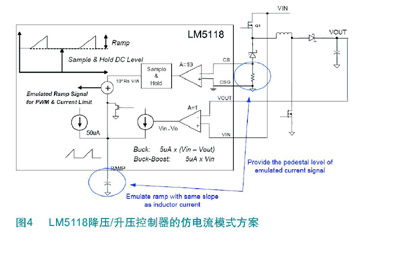
2.Can silk printing with your LOGO. Simply attaches with double sided adhesive that can be removed later.
3.Fits: Computers, Laptops, Smart TV's, PS4, Xbox, 3rd party external webcams
4.Protects your webcam from scratches. Made from high-grade durable ABS.
5.cheap price custom logo camera Webcam Cover for laptop computer