Today, to get a glimpse of the signal integrity in engineering design, Bala sees five typical problems encountered in engineering design. Not because of these tangled, it should not start SI design. It is believed that the engineering lions who have been on the move will have a resonance!
Category 1 issues: Must rely on simulation issues
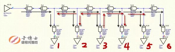
Some problems, when designing for the first time, if you do not rely on simulation, there is no good way to know if you can't do it or if you have any danger. Take a common chestnut: drag a multi-topology structure, this is a design scene with a high probability of occurrence. If there is a main control board, and six boards are dragged through the backplane (some companies call the backplane), if it is the first time, how can we evaluate this scheme? By design rules? Rely on the rule of thumb? By guessing? That is purely a big win. Of course, some people will say, try it out with a try. Of course, but like this kind of system-level solution, the cost and cycle time of boarding are almost unacceptable (except for Tyrant, of course). To evaluate the feasibility of the program in advance, theoretical analysis is indispensable, but this problem is only determined by theoretical analysis.
Let's start with a theoretical look at what will happen in this topology. The input buffer of the chip usually shows a very high impedance to the signal, and the signal is reflected to the receiving chip. The six receivers in the figure below have reflections. The reflected signal encounters two split paths when it encounters the bifurcation of the trace. For example, the signal reflected from the 3 is transmitted along the main trunk in both the right and left directions. When it is transmitted to receivers such as 1, 2, 4, 5, and 6 Reflection occurs. That is, 3 reflected signals interfere with the received signals of other chips. Similarly, any other receiver's reflected signal will interfere with other receivers. The reflection process occurs many times, delays superimposing, and repeated reflections and oscillations. This is a complicated process. It is theoretically simple, but eventually it will superimpose a thing or something. Can not think of it, rely on software.
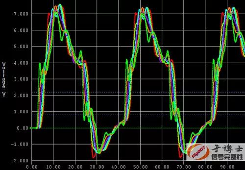
If you do not do any processing, the waveform looks like? Simple simulations can reveal obvious risks. See the figure below. High and low levels are rushed too much and there are hidden dangers.
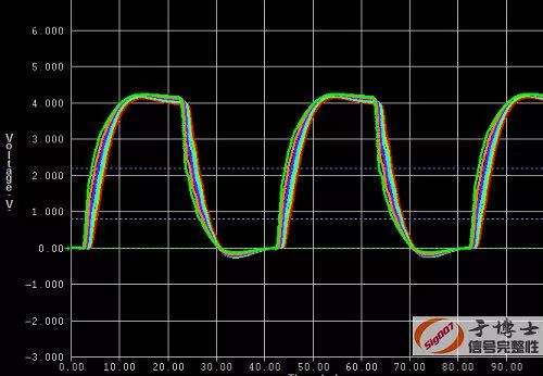
Through simple processing, we can reduce the reflection signal to repeatedly oscillate between receivers. We can make this waveform look like this. This is more confidence. There are many problems that require simulation, and it is very effective to avoid risks through simulation.
Category 2 issues: Problems that cannot be simulated or are difficult to simulate
Simulation is a very effective means of signal integrity design. The simulation software is amazing and it has captured a large number of engineers.
If this thing is so simple it would be great, click, click, click..., OK, live, and more cool!
How can such a wonderful world!
Over-reliance on simulation, when working hard will often encounter tangled pain. In particular, when positioning itself as a simulating engineering lion, in the face of problems, sometimes there is no place to start, and you do not know what to imitate. If you really want to encounter such a thing, you should think it over. There are things that you can't really do. Maybe you are facing this type 2 problem.
For example, the chestnut below is very sour, but it is absolutely delicious without sugar.
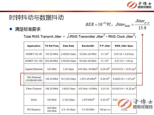
Some boards have individual clock signals that require very high jitter. If the clock jitter is large, the error test will not pass. High-speed serial interfaces are required for clocks. Let's take a look at the jitter of typical interface signals. The jitter contribution of the clock signal to the transmission signal cannot be ignored. Then the problem came, the hardware staff to throw this problem to you, how to solve does not matter, the hardware is the result, get on the line. So how do you handle this? By simulation? How to imitate? What to imitate?
Before starting work, analyze the factors that will affect the jitter of the clock and list the main factors:
1, reflection (the reflection of evil, which has it)
2, crosstalk (all evil crosstalk, which has it)
3, modal transformation (pay attention to the impact)
4, reference plane (hidden minefield)
5, differential pair design (by many people ignore)
6, the clock chip power (emphasis)
7, layer structure to arrange the layout of the wiring layer (a variable to read the difference)
8, the clock crystal oscillator selection (hardware selection will be cautious, usually without SI personnel processing)
9, crystal power processing (can not be ignored)
Other Layout-related details do not say, just above mentioned enough to simulate engineering lion drink a pot (whole point Erguotou or vodka?).
Well, simulation engineering lion, simulation engineering lion, open imitation. Open magical software, and then, no then......... What do you plug into the software to run simulations?
What is that, the impact of power on the jitter, the simulation swollen? The impact of the reference plane, the simulation swollen? It's inevitable to do headaches from a simulation point of view. But if you change a character, you will see it from the perspective of a signal integrity design engineer. The simulation of the simulation can not be implemented if the control can't be simulated (lan). Anyway, the final result is just one result. The jitters will be reduced.
It is a good cat that the black cat catches the mouse. Good products are designed and not imitated. Not tangled, do a good cat!
Category 3 problem: simulations are needed but not by a single simulation
Take a typical chestnut... Keke, it's chestnut, enough, it was shot.........
Well, the blue-swept-faced swaddle came back and said. The magnetic beads of the power supply filter (again, all kinds of magnetic bead filter), saying that the magnetic bead filter on the power supply is everywhere, saying that this magnetic bead filter eats much of the overtime time of the hardware personnel, debug debugging and debugging, debugging to collapse. Can you steal lazy?
Brought magical simulation software, click, click, click... ...OK. This is a beautiful frequency response curve. The blue one is designed well. Swearingly to say, lazy, the old copy of the direct copy, did not re-map, was photographed flying.........
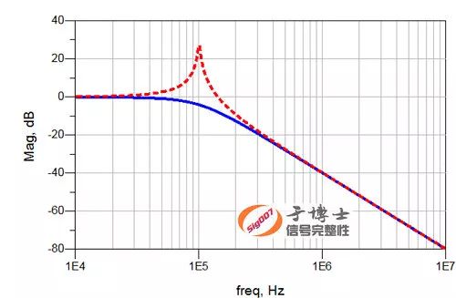
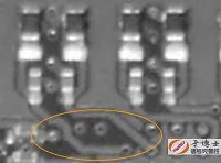
Completed? Really completed? Hey, don't be too happy. A lot of evil bugs are waiting in line to prepare for digging. Like the image below, where the magnetic beads and the small tail pulled out of the capacitor, where do you put it? How long is Lado?
It is certainly not very good to pull the cable too long. Earth people know it. Just imagine what would happen if this small tail passed right through the circuit board inlet power copper skin?
So the adjacent plane layer should be considered. If you put it on the surface layer, then the planar layer next to it is preferably GND. If arranged on the inside? The inner power plane layer is often fragmented. If this bead filter is used more, it may not fit. If the plane layer cannot be placed, the signal layer will have to be placed. The problem is again, sandwiched between the upper and lower planes, and there will be other signal lines next to it. This is a pit. Be careful.
The simulation of this problem can solve the selection problem of magnetic beads and capacitors. To avoid those pits, you cannot rely on simulations. Only the layout can be carefully controlled.
Category 4 issues: details of the need for risk monitoring
What's the old saying? The devil is hidden in the details! Yes, it's a devil. It's definitely a devil! Many devils will make you have to passionately go to work overtime.
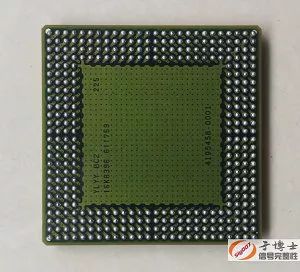
The PCB is a three-dimensional structure. Don't always think of PCBs with planar thinking. Not lofty, on the map, see for yourself. The pictures taken out of the courseware, saying that every time I teach this lesson, I will talk for a long time.

Category 5 Problem: Overall Planning Before Layout
Instead of narrating Luo Luosuo sou, the entire one with a Tang Yan like recruitment, and old to relive one thing that happened a long time ago. One day in history, a certain gentleman called and gave him a difficult problem.
Someone: Yu Yu, I have a board to shoot, and I don't trust it. I want you to look at it.
Old in: Hey situation, talk!
Jun: There are 10G differential interfaces on the board, with DDR3.
Older: 10G is a single lane or an interface...
Someone: Single lane.
Older: Well, you know, you continue.
Someone: I took the 10G differential pair in several inner layers close to the top, and the DDR3 signal line took the inner layer near the bottom.
Older: Don't you put the 10G differential pair on the inner layer of the bottom? Risky, adjust the alignment layer!
Someone: The differential is set to the line width of the line, and it must be transferred to the following layers. The impedance can't control 100 Euro...
In the old: you DDR control to 40 European?
Someone: Yes.
Old Yu: Communicate with the board and re-determine a stack. It doesn't take much effort.
Someone: The cascades are all set and cannot be changed.
Older: Make a back drill.
Someone: The hole under the BGA is too small to be insecure.
Older:...
If you make a plan before the board is drawn, which signal goes which signal layer, which plane layer puts GND, which plane layer puts power, it is not so tangled.
There was no pit and he dug himself one.
There are many similar issues, do not underestimate this, the overall plan can avoid a lot of unnecessary trouble.
Category 6 issues
Then Bala, the next question is... Ah ..., was shot again.........
Well, if you don't have Bala, will you still work? Who took my soldering iron... and returned it to me... No one will stop. Today, I must put all these balls down...
MTB-CUT 180T Screen Protector Machine
China MTB-CUT 180T Screen Protector Machine,Hydrogel Protector Machine supplier & manufacturer, offer low price, high quality Cell Phone Screen Protector Machine,Mobile Phone Screen Protector Machine, etc.
For any specific device model, it may cut screen protectors according to the necessary pattern. Once you connect it to the internet, it will update all of the stored data. Likewise, this screen protector cutter can get new device screen sizes from the internet if a design is not recognized.
Certification: CE, RoHS; Superiority and Core Features of this cutting machine as below.1. One cutting machine for all brands and all models screen and even back films.
2. Self owning system source code & Flexible operating system.
3. Online date update for any new models.
4. Factory direct sales model to distributors all over the world.
5. Providing premium quality screen protector.
6. Offering one-stop service from before to after sales.
Mtb-Cut 180T Screen Protector Machine,Hydrogel Protector Machine,Cell Phone Screen Protector Machine
Mietubl Global Supply Chain (Guangzhou) Co., Ltd. , https://www.mietublmachine.com