How to obtain the true PA input impedance of a high-power RF signal
The input impedance of a non-ideal PA (power amplifier, power amplifier) ​​is measured in a load-pulling system using a source-pulling method. This method does not have the inaccuracy caused by measuring the impedance of the device. However, the multi-point measurement and dual-port S-parameter test method for source and load tuners can extract the true PA input impedance of the RF signal power level on the probe / device reference plane.
As people pay more and more attention to integrated RF power applications, accurate characterization of on-chip components becomes critical to the successful implementation of integrated circuit design. Especially for PA, this problem is more complicated. The high power level of the last stage of the transmission path determines various special attributes of the PA. One of them is its low input impedance, which changes with the power level. In general, we use a load-pull system to measure the impedance of on-chip components, or other devices that are not 50Ω ideal impedance.
In a load-pulling system, the source impedance with the smallest return loss is usually regarded as the conjugate impedance of the DUT (device undertest, device under test). If the return loss is indeed on the reference plane of the DUT, then using this impedance value is accurate. However, since the echo power is measured on the reference surface of the source tuner, people use different methods to extract or "de-embed" the echo on the DUT reference surface from the echo power measured on the tuner reference surface frequency. Unlike input and output power de-embedding methods, echo power de-embedding is very phase sensitive. This makes de-embedding return loss only an approximate result, but this result is accurate only when the tuner loss is negligible.
Analysis and methods
For simplicity, it is assumed that there is an ideal (that is, purely resistive) source impedance of 50Ω on the reference plane of the tuner. Figure 1 shows the basic definitions of the source tuner reference plane, DUT input reference plane, DUT output reference plane, Γo, Γtuner, Γs, and ΓDUT. For convenience of description, we refer to the source tuner reference plane as the "tuner reference plane" and the DUT input reference plane as the "DUT reference plane." Here, only the input path is analyzed.
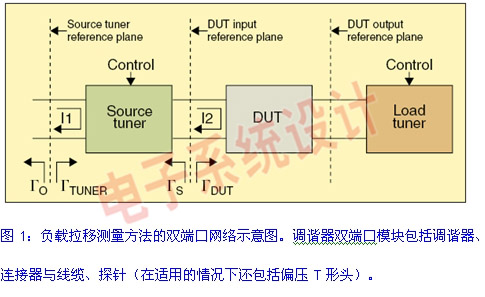
The mathematical relationship between the reflection coefficient (Γ), S-port parameters (S), impedance (z), and return loss (RL) in Figure 1 is as follows:
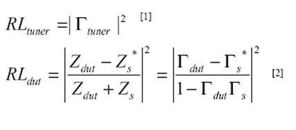
Our goal is to find the relationship between RLtuner and RLDUT:
due to
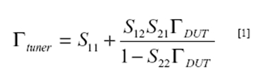
It satisfies
Where Sij is the dual-port S-parameter of the source tuner module, which connects the reference plane of the tuner and the reference plane of the DUT.
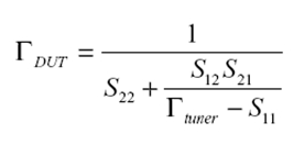
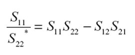
After simplification, available 
Obviously, this is a function of Γtuner amplitude and phase. This phase relationship does have a vanishing point, it appears in the following situations
Further analysis shows that this condition is equivalent to an ideal matching network (ie, the conjugate matching on the second port produces an impedance of 50Ω on the first port). This condition is not true in the high-loss region at the edge of the Smith chart, because tuners with internal taps near the center of the transmission rod have higher losses.
Another approximation used in the measurement process is to assume that the echo power is negligible. In this case, there is no problem with the phase difference. However, the magnitude of the return loss measured from the load-pulling system is usually large enough to overturn this assumption. Moreover, the avoidance loss will change with the change of power, because the impedance of the DUT changes with the change of power. Therefore, the return loss cannot be kept low in the entire scanning range of the RF power level.
Usb Common Mode Choke,Magnetic Ring Inductor,Ferrite Core Inductor,Coilcraft Inductor
IHUA INDUSTRIES CO.,LTD. , https://www.ihua-inductor.com