The calculation of theoretical line loss involves a lot of data, and the calculation task is heavy. If it is calculated manually, in most cases, only a simple route can be roughly calculated, but it is difficult to handle a complex route. Therefore, it is necessary to use mature computer hardware and software technologies to transform complex calculations into simple computer operations. Under the premise of ensuring calculation accuracy, the efficiency of calculations is fully improved. In order to achieve the institutionalization of theoretical line loss calculations, Standardization and standardization lay a solid technical foundation.
Based on the Visual Graph system of Graph King Software, our company has developed theoretical line loss calculation and comprehensive management software products to meet the requirements of different power supply companies for line loss calculation and management. The system covers functions such as drawing management, theoretical calculation, line loss statistics and analysis, especially the powerful drawing function in drawing management, making the most popular "language" in the power industry-electrical wiring diagrams, as the main user interface, combining many This algorithm makes the original abstract theoretical calculation very intuitive and easy to operate. In addition, based on the wiring diagram, it can also be extended with many practical functions, such as power outage notification, equipment account statistics and so on.
Considering the data sharing requirements within the power supply bureau, the software is designed based on the network and large database platform, and can be operated stably between the local area network within the bureau or between the bureau and the power supply station with worse communication conditions.
System structure diagram:
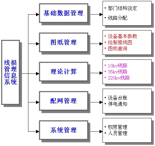
1. Basic Data Management
1. Department structure setting
Edit and modify the structural relationship between various departments within the power supply bureau.
2. Line allocation
Distribute the outlet of the substation to the designated power supply station, clarify the lines managed by each power supply station, and establish the corresponding statistical relationship.
2. Drawing management
1. Basic parameters of equipment
Enter the model and basic parameters of the power components to be used in the drawing process to prepare for the selection of the corresponding component model when drawing in the future. The basic parameters of the main equipment are entered in the system database, and the user can directly call them; for the uncommon equipment or customized equipment, the user can add through this module.
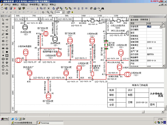
2. Draw wiring diagram
Each electrical component is designed with a corresponding national legend. The entire drawing process is to select different component legends with the mouse and place them in the drawing. The drawing supports standard A4, A3, A2, A1, and custom sizes. You can zoom, choose to print all or part.
With the completion of the drawing, the circuit topology data and corresponding equivalent circuit diagrams required for theoretical calculation are automatically processed by the program and recorded in the database. There is no need to manually edit and enter the topology data such as node numbers, which greatly reduces The workload of theoretical calculation.
Due to the use of the most advanced vector graphics technology and special optimization for the drawing characteristics of the power industry, the work of drawing circuit diagrams is greatly simplified, especially the topology processing required for theoretical calculations is "unconsciously" by users Automatically completed. The use of the software is also very easy, simple training can be used to operate, the complexity of use is far lower than the common design software.
The drawing is divided into grid system wiring diagram and 10KV circuit diagram.
System wiring diagram:
3. Drawing query
The personnel of each department in the bureau can share the drawings and materials through the network, and those who do not have the authority to modify the wiring diagram can consult the drawings and materials.
In the review state, you can only search and read the drawings, and cannot modify them. It is suitable for daily call and use of drawings, you can view the network and the parameters of various electrical components, and you do n’t have to worry about the wrong operation to modify the drawings.
3. Theoretical calculations
Theoretical calculation provides three algorithms for selection:
? Average current method (10KV, 35KV line)
? RMS current method (10KV, 35KV line)
? Electricity method (10KV line)
Here not only provide a variety of algorithms for different voltage levels, but also particularly consider the current situation of small power supplies that are commonly available to access the Internet through 10KV or 35KV lines. In the calculation, the theoretical line loss on the line can be calculated according to the three conditions of small power supply stopping power generation during the dry season, small power supply and substation common power supply, and small power supply independent power supply, so as to accurately reflect the impact of small power supply on line loss The actual operation of the line.
According to the actual situation of the line, different algorithms are selected for theoretical calculation, and the theoretical line loss value can be calculated by entering the operating data. At the same time, the system also retains the loss details of each component in the calculation. Combined with the circuit diagram, you can clearly understand the loss of each line segment and distribution transformer in the line, which is convenient for loss reduction analysis. As shown:
There are three methods for calculating the 10KV line, and you can select the appropriate algorithm according to the actual situation of the line. After the calculation, the calculation results of transformer loss, wire loss and line loss rate will be displayed on the interface. You can click the component loss details to view the detailed loss of all components in this calculation, or you can view the loss of other lines in the online loss comprehensive query, and compare it with this calculation. The program can automatically find out the small power supply on the circuit diagram. As long as the operation data of the corresponding small power outlet is input, the small power supply can be included in the theoretical calculation.
There are two methods for calculating 35KV lines. In the actual power grid, the 35KV network is usually operated in open loop, and multiple main transformers separately supply power to each part of the 35KV network. In this regard, the software will automatically search for the grid wiring diagram, list all the 110KV or 220KV main transformer 35KV side gate table in the grid, prompt to enter the relevant operating data.
As with the 10KV line calculation, the software will also automatically process the small power supply that appears on the grid wiring diagram, and you can also view the loss of all components in this calculation through the component loss details. Through the comprehensive query of line loss, you can view the loss of 35KV lines in the past months and compare and analyze with this calculation.
For the power supply bureau with SCADA system, the operation data required for calculation can be obtained from the SCADA system, which will improve the accuracy and precision of the calculation.
4. Distribution network management
Linking circuit diagrams with equipment accounts, power outage notices and other services can more effectively standardize the entire power business system.
1. Equipment ledger
In the process of drawing, line components have been recorded in the database. You can select different statistical standards and components that need to be counted to make a combination of ledger statistics in a variety of ways. You can sort by substation and power supply, and list the number of devices and the components of each component. Other data is accurate, convenient and easy to manage.
2. Outage notification
After adding the power supply user data on the basis of the line map special change and public change data, you can manually or automatically send outage notices during outages, query historical outage records, facilitate outage management, and achieve effective scheduling.
V. System maintenance
Add, delete, modify actions to the system operators, and set permissions for them. The power management system is of a certain confidential nature. The system should be operated by specialized personnel. The password is not suitable for many people to know. For security, the password should be changed from time to time.
Variable Frequency AC Power Supply
Variable Ac Power Supply,Variable Frequency Power Supply,Ac Power Supply Variable Voltage,Ac Power Supply With Variable Frequency
Yangzhou IdealTek Electronics Co., Ltd. , https://www.idealtekpower.com