1 Introduction
Today, energy conservation, emission reduction, and environmental protection have become the consensus of all countries in the world. According to the International Energy Agency (IEA), commercial and residential lighting accounts for 20% of the world's annual electricity generation. As a result, countries around the world are working to replace low-energy existing light sources with more energy-efficient solutions [1–3]. Light-emitting diodes (LEDs) have the advantages of low energy consumption, high lumens, long life and low pollution. As technology advances and manufacturing costs continue to decline, LED lighting has become a highly attractive alternative light source solution [4]. In recent years, LED lighting has not grown in the general lighting industry. According to the IEC-1000-3-2-C current harmonic limit standard promulgated by the International Electrotechnical Commission, high power factor and low input current harmonics become mandatory design requirements for AC-powered LED drivers [5]. In recent years, many scholars have proposed a variety of PFC topology and control strategies for LED drivers [6 ~ 7]. In response to the demand for dimming in LED lighting, a few manufacturers have introduced a dimming method based on DC LED illumination, which adjusts the current flowing through the LED in a continuous or intermittent manner to change the brightness of the LED light. The product must be AC/DC converted before it can be used in the existing power mode (AC2200V 50Hz or AC110V 60Hz). With the advancement of LED lighting technology, research on AC LED lighting is in the ascendant, but the dimming method under AC LED lighting is rarely reported in the literature [3]. This paper briefly analyzes the working principle of phase control and PWM dimming mode in AC LED illumination, and carries out experimental comparison analysis.
2 phase control dimmer
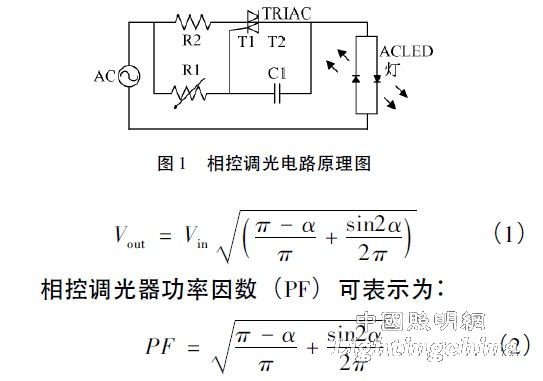
A dimmer is a common power electronic lighting device that is used extensively in commercial and residential lighting, and has the advantages of ease of use and energy saving. The widely used dimmers in lighting mainly use thyristor control technology, and the circuit working principle has two methods of leading edge and trailing edge phase control [4]. Figure 1 shows the basic circuit of a thyristor phase-controlled dimmer. AC is an input power frequency of 220V AC, and the load is AC LED. T1 and T2 are two thyristors or a triac TRIAC, and the adjustable resistor R1 and Capacitor C1 forms a thyristor gate trigger circuit. After the sine wave input voltage crosses the zero point, the delay is a period of time, that is, when the phase control angle is (α), the thyristor T1 is triggered to turn on, and when the next AC voltage crosses zero, T1 is inverted and turned off; then, to the next When the phase control angle (α) is triggered, the thyristor T2 is turned on again. When the next AC voltage crosses zero, T2 is reversed and cut off, so that it works repeatedly. The output voltage of the phase-controlled dimmer is given by equation (1):
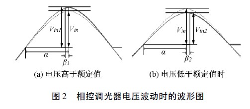
In order to simplify the analysis, only the operation of the input voltage in the positive half cycle is discussed, and the operation of the negative half cycle is similar. According to the circuit principle, the phase control angle (α) of the thyristor is related to the time delay circuit composed of R1 and C1. When the parameters of R1 and C1 are unchanged, the influence of the input voltage fluctuation on the trigger phase control angle is shown in Fig. 2. Input voltage (blue dotted line) The normal amplitude is Vin. At some point, due to the grid voltage fluctuation, the voltage amplitude rises to Vin1 (blue solid line). At this time, the trigger phase angle is reduced to (α - β1), the angle (β1) is the result of the increase of the input voltage to Vin1, and the output voltage Vout (red thick line) also becomes larger, as shown in Figure 2 (a). When the voltage amplitude drops to Vin2 (solid blue line), the trigger phase angle increases to (α + β2), and the angle (β2) is the result of the line voltage dropping to Vin2. The output voltage Vout (red thick solid line) also drops accordingly, as shown in Figure 2 (b). Thus, when the line voltage fluctuates, the phase-controlled dimmer will amplify the brightness of the light.