Introduction
Measuring the current flowing through the sense resistor seems simple. Amplify the voltage and read it with the ADC to know what the current is; but if the voltage across the sense resistor is far from the system ground voltage, the detection becomes more difficult. A typical solution is to eliminate this voltage difference in the analog or digital domain. But here is a different approach - wireless.
Analog current sense ICs are compact solutions, but the voltage difference they can withstand is limited by semiconductor processes. It is difficult to find a device with a rated voltage exceeding 100V. These circuits cannot be accurately measured if the sense resistor's common-mode voltage changes rapidly or swings up and down the system ground.
Digital isolation technology (magnetic or optical) is a bit bulky, but works with high precision and can typically withstand thousands of volts. These circuits require an isolated power supply, but sometimes it can be integrated into the isolator. If the sense resistor is physically separated from the main system, long wires or cables may also be used.
The wireless current sensing circuit overcomes many of the above limitations. Let the whole circuit float with the common mode voltage of the sense resistor and wirelessly transmit the measured data in the air, and the voltage limit will not be discussed. The sense resistor can be located anywhere without the need to route cables. If the power consumption of the circuit is very low, then even a separate power supply is not required, and a small battery can make it run for many years.
Design overview
Figure 1 shows a block diagram of the design. The current sensing circuit is based on a chopper stabilized operational amplifier LTC2063 that amplifies the voltage drop across the sense resistor. The AD7988 micropower SAR ADC digitizes the value and reports the results via an SPI interface. The LTP5901-IPM is a radio module that contains not only radio but also the networking firmware required to automatically form an IP mesh network. In addition, the LTP5901-IPM has a built-in microprocessor to read the AD7988 ADC SPI port. The LTC3335 is a low power DC-DC power supply that converts battery voltage to a constant output voltage. The LTC3335 also contains a coulomb counter to report the accumulated charge taken from the battery.
figure 1
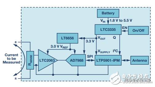
Figure 1. The low-power wireless current-sense circuit consists of a low-power chopper op amp (to amplify the sense voltage), digitized with a low-power ADC and a reference, and connected to a SmartMesh IP radio. Battery output to a low-power DC-DC converter to obtain a constant power supply while recording the charge drawn from the battery
Signal chain
The LTC2063 is an ultra-low power chopper-stabilized operational amplifier with a maximum supply current of 2μA, making it ideal for battery-powered applications. The offset voltage is less than 10μV, so it can measure very small voltage drops without losing accuracy. Figure 2 shows the LTC2063 configuration used to amplify and level shift the voltage across the 10 mΩ sense resistor. Select the appropriate gain to map the sense resistor's ±10 mV full-scale input (corresponding to ±1 A current) to the full-scale range near the output, centered at 1.5 V. This amplified signal is input to a 16-bit SAR ADC. The AD7988 was chosen for its extremely low standby current and good DC accuracy. At low sample rates, the ADC automatically shuts down between conversions, with an average power consumption as low as 10 μA at 1 kSPS. The LT6656 is used for bias amplifiers, level shifting resistors, and ADC reference inputs. The LT6656 reference consumes less than 1 μA and can drive up to 5 mA with very low dropout voltage, making it easy to output a precision 3 V even with a 3.3 V system supply.
There are three approximately equal sources of offset error in this signal chain that together contribute approximately 0.5% of the error relative to the ±10 mV full-scale input. This includes the offset voltages of the LTC2063 and AD7988, as well as the level shifting resistor mismatch (recommended 0.1% resistor). A single point calibration can largely eliminate this offset. Gain errors are generally dominated by the inaccuracies of the available sense resistors, which tend to be worse than the 0.05%, 10 ppm/°C specifications of the LT6656 reference.
figure 2
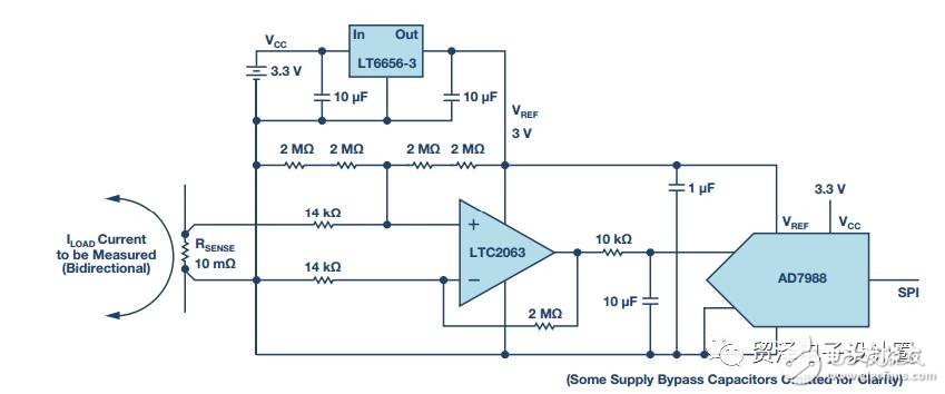
Figure 2. The current sense circuit is floating with the sense resistor voltage. The chopper op amp LTC2063 amplifies the sense voltage and biases it to the middle rail of the AD7988 ADC. The LT6656-3 provides a precision 3 V reference.
Power management
The LTC3335 is a nanoscale power buck-boost converter with integrated coulomb counter. It is configured to generate a regulated 3.3 V output from an input supply of 1.8 V to 5.5 V. This allows the circuit to be powered by two alkaline primary batteries. For duty cycle wireless applications, the load current can vary from 1 μA to 20 mA, depending on whether the radio is in active or sleep mode. The LTC3335's static power consumption at no load is only 680 nA, so when the radio and signal chain are in sleep mode, the overall circuit consumes very little power. In addition, the LTC3335 can output up to 50 mA of current and easily provide enough power during radio transmission/reception, making it suitable for a variety of signal chain circuits. The LTC3335 also has a built-in coulomb counter, which is very convenient. When switching, it records the total charge taken from the battery. This information can be read through the I2C interface to predict when the battery needs to be replaced.
Wireless networking
The LTP5901-IPM is a complete radio module that includes a radio transceiver, embedded microprocessor and SmartMesh IP networking software. The LTP5901-IPM performs two functions in this application: wireless networking and management (process). When multiple SmartMesh IP terminals are powered on near the network manager, these terminals automatically recognize each other to form a wireless mesh network. The entire network automatically performs time synchronization, which means that each radio is powered up only for a very short specific time interval. Therefore, each node is not only a source of sensor information, but also acts as a routing node to pass data from other nodes to the manager . This results in a highly reliable, low-power grid network with multiple paths from node to manager, but all nodes (including routing nodes) have very low power consumption.
The LTP5901-IPM includes an ARM® Cortex® M3 microprocessor core running networking software. In addition, users can write application firmware to complete tasks specific to the user application. In this example, the microprocessor inside the LTP5901-IPM reads the SPI port of the current measurement ADC (AD7988) and the I2C port of the coulomb counter (LTC3335). The microprocessor can also place the chopper op amp (LTC2063) in shutdown mode, further reducing its power consumption from 2 μA to 200 nA. This saves more power in applications where the measurement interval is extremely long.
Total power consumption
The total power consumption of a complete application circuit depends on a number of factors, including how often the signal chain takes a reading, how the node is configured in the network, and so on. For a terminal that reports once per second, the typical power consumption of the measurement circuit is less than 5 μA, and the typical power consumption of the radio may be 40 μA, allowing a small battery to operate for years.
image 3
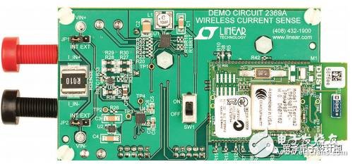
Figure 3. A complete wireless current-sense circuit implemented on a small PCB. The only physical connection is the banana socket for the current to be measured. The radio module is shown on the right. The circuit is powered by two AAA batteries connected to the back of the board.
in conclusion
The combination of Linear Technology and Analog Devices' signal chain, power management, and wireless networking products allows us to design true wireless current sensing circuits. Figure 3 shows an implementation example. The LTC2063, a new ultra-low power chopper op amp, accurately reads small voltage drops across the sense resistor. The entire circuit, including the micropower ADC and the reference, floats along with the common-mode voltage of the sense resistor. With a small battery, the nano-powered LTC3335 switching regulator can power the circuit for years, while reporting the cumulative battery usage using a built-in coulomb counter. The LTP5901-IPM wireless module manages the entire application and automatically connects to a highly reliable SmartMesh IP network.
Author:
Kris Lokere is a strategic application manager for signal chain products, joining ADI as a result of the merger of Linear Technology. Kris likes to use multiple product line technologies for system architecture design. For the past 20 years, he has been responsible for designing operational amplifiers, forming engineering teams, and managing product line strategies. He holds several patents and holds a master's degree in electrical engineering from the University of Leuven and an MBA from Babson College.
The biggest feature of the temperature regulating valve is that it only needs an ordinary 220V power supply and uses the energy of the regulated medium to directly automatically regulate and control the temperature of steam, hot water, hot oil and gas. It can also be used to prevent overheating or heat exchange. The valve has the advantages of simple structure, convenient operation, wide temperature regulation range, fast response time and reliable sealing performance, It can be adjusted at will during operation, so it is widely used in hot water supply in chemical industry, petroleum, food, light textile, hotels and restaurants.
Temperature Regulating Valve,New Needle Valve,Marine Butterfly Valve,Valve Pressure Gauge
Taizhou Jiabo Instrument Technology Co., Ltd. , https://www.taizhoujiabo.com